Drive End Frame Disassembly Procedure
This section is applicable only to the CS-144 generator. The CS-130D
generator cannot be overhauled. Refer to
Generator Usage
.
Tools Required
J 39200 Digital
Multimeter
- Scribe a mark in the frame end parts to help locate the parts
in the same position during re-assembly.
- Remove the four through-bolts.
Notice: On models with a slip ring end ball bearing on the rotor shaft, this
bearing must be replaced with a new bearing any time the two halves of the
generator are separated. If not replaced, the bearing may bind
and fail due to distortion of its outer tolerance rings. This does not apply
to roller-type slip ring end frame bearings.
- Separate the rotor and drive end frame assembly from the slip ring end
frame assembly.
Notice: The rotor may be distorted if the vise is overtightened.
- Place the rotor in a vise. Tighten the vise to the rotor only enough
to allow removal of the pulley nut.
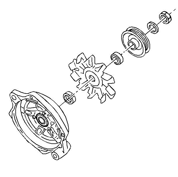
- Remove the following parts
from the rotor shaft:
- Remove the drive end frame and the inside collar from the rotor
shaft.
Slip Ring End Frame Disassembly Procedure
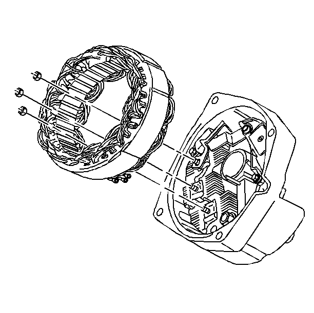
- Remove the three nuts
securing the stator to the rectifier bridge.
- Remove the stator from the slip ring end frame .
- Unsolder the following connections to the voltage regulator:
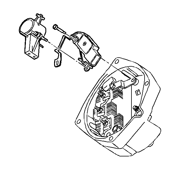
- Remove the insulated screw
from the brush holder.
- Remove the voltage regulator screw.
- Remove the brush holder with the dust shield.
- Remove the voltage regulator from the slip ring end frame.
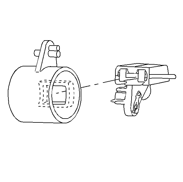
- Remove the following components from the brush holder:
- Clean the brushes with a soft, dry cloth.
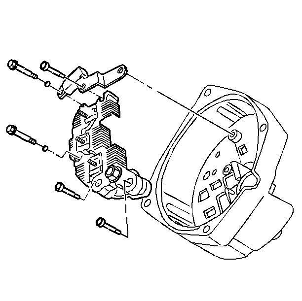
- Remove the rectifier bridge and capacitor as a unit:
| 10.2. | Remove the washers. |
| 10.3. | Remove the rectifier bridge and capacitor assembly. |
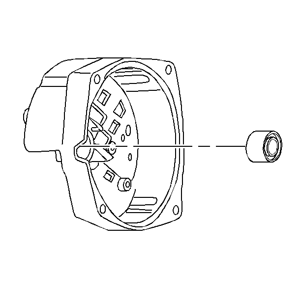
- Remove the slip ring end frame bearing.
Cleaning and Inspection Procedure
- Clean all of the metal parts, except the voltage regulator, the
rectifier bridge, the stator, the rotor, and the bearing assemblies, in a
suitable solvent.
Wipe or blow dry the parts.
- Remove the dust shield and brushes from the brush holder.
- Inspect the brush holder for damage.
- Inspect the brush springs for a broken wire or corrosion.
- Inspect the brushes for wear.
| • | If the brushes are worn to 11 mm (0.4 in) or less
in length, replace the brush holder assembly. |
| • | Use a retainer pin to hold the brushes in the holder. |
- Inspect the slip ring end of the rotor shaft for overheating or
scoring.
| • | If signs of overheating or scoring are present, replace the rotor. |
| • | Any time the two halves of the generator are separated, replace
the slip ring end bearing. |
- Inspect the drive end bearing for roughness, looseness, or wear.
If the condition of the bearing is in doubt, replace the generator drive end
frame.
- Inspect the windings for burned insulation.
| • | Replace the rotor or the stator if either of these look burned. |
| • | Burned insulation appears as very dark or blackened wiring. A
strong acidic odor will be apparent. |
- Inspect the terminal connectors for corrosion or breaks.
- Inspect the windings on the stator for chipped insulation.
If the chipped area is small, and the rest of the stator is operating
properly, repair the stator with insulating varnish.
- Inspect the slip rings for scoring, wear, or pitting.
| 11.1. | If the rings are dirty, clean the rings with 400 grain
or finer polishing cloth. |
| 11.2. | Spin the rotor. Hold the polishing cloth against the slip rings
until the rings are clean. |
| 11.3. | Blow all dust away. |
| 11.4. | If the rings are scored, worn, or pitted, replace the rotor. |
- Inspect the generator housing for cracks, warping, or other damage.
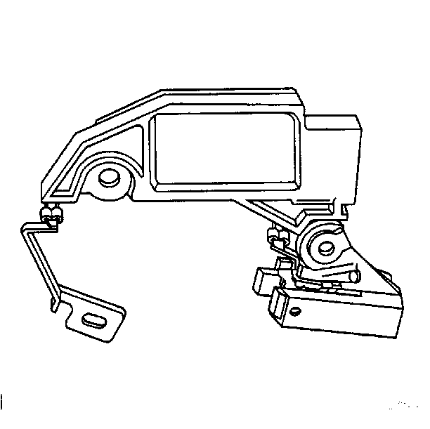
- If the regulator, the
brush assembly, or the connector needs replacing, unsolder the regulator
from the other two components. Use as little heat as possible in order to
protect the regulator.
Rotor Field Winding Tests
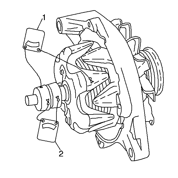
- Connect a J 39200
DMM from one slip ring to the rotor shaft. Measure the resistance. Refer to
Generator Usage
. If the reading is less than specified,
the rotor winding is grounded. Replace the rotor.
- Connect a J 39200 DMM from one slip ring to the other slip
ring. Measure the resistance. Refer to
Generator Usage
.
If the reading is greater than specified or infinite, the winding is open.
Replace the rotor.
Stator Tests
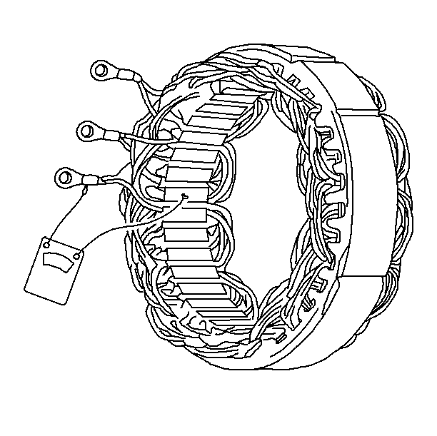
- Connect a J 39200
DMM from any stator lead to bare metal on the stator frame. Measure
the resistance. If the J 39200 does not read infinity, the stator is
grounded. Replace the stator if it is grounded.
A J 39200 cannot be used to test for open stator windings or
shorts between windings because the stator is delta-wound.
- Inspect the stator assembly for noticeable discoloration. Discoloration
usually indicates an abnormal condition in the stator windings. Replace the
stator if it shows discoloration.
Rectifier Bridge Test
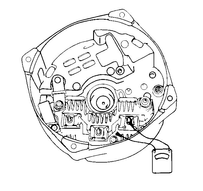
- Connect a J 39200
DMM to the grounded heat sink and one of the three terminals.
Note:
Some digital ohmmeters cannot be used
to test diodes in the rectifier bridge. Consult the ohmmeter manufacturer
in order to determine the capabilities of your ohmmeter.
- Place the J 39200 DMM in the diode test position.
- Press down firmly on the flat metal clip.
- Observe the diode reading.
- Reverse the J 39200 lead connections to the grounded heat
sink and the same metal clip. If both readings are the same, replace the rectifier
bridge. A good rectifier bridge will give one high and one low reading.
- Repeat this procedure between the grounded heat sink and the
other two terminals, and between the insulated heat sink and each of the
three terminals. This makes a total of six tests, with two readings taken
for each test.
Regulator
The regulator cannot be tested outside of the generator. Replace the
regulator if any of the following conditions apply:
| • | If the rotor, the stator, and the rectifier bridge operate properly,
but the generator produces more than 16 volts. |
| • | The generator cannot produce the load test amps shown in
Generator Usage
. |
Slip Ring End Frame Assembly Procedure

- Install the bearing into the slip ring end frame from the outside.
- Ensure that the bearing is flush with the outside shoulder of
the slip ring end frame.

Important: To ensure proper operation of the generator, install the slip ring end
frame components in the correct order.
- Install the rectifier bridge.
Important: Install the capacitor with the insulator material contacting the end
frame.
- Install the capacitor.
- Install the washers.
Important: Ensure that the insulated bolt attaches the capacitor strap and the
rectifier bridge to the slip ring end frame. Ensure that the metal side of
the capacitor strap is contacting the regulator connection.
- Install the bolts.

- Install the brushes into
the brush holder with the retaining pin.
- Install the dust shield onto the brush holder.

- Install the following components into the slip ring end frame as one
unit:
- Ensure that the brush retaining pin extends through the end frame
access hole when the brush holder is in place. After the rotor and the drive
end frame are installed, the pin will be removed, allowing the brushes to
contact the slip rings.
- Install the regulator bolt.
- Install the brush holder bolt.
- Assemble the connector strap to the voltage regulator solder clip.
Assemble the brush holder connection to the other voltage regulator solder
clip.
Notice: Avoid excessive heat when soldering connections, as this can cause voltage
regulator damage.
- Crimp, then solder, the voltage regulator connections.

- Install the stator into
the end frame. Align the three stator leads to the three rectifier bridge
terminals.
- Install the three rectifier bridge nuts. Tighten the nuts securely.
Drive End Frame Assembly Procedure
- Install the inside collar onto the rotor.
- Install the rotor into the drive end frame.

- Install the following
components onto the rotor shaft:
Notice: Use the correct fastener in the correct location. Replacement fasteners
must be the correct part number for that application. Fasteners requiring
replacement or fasteners requiring the use of thread locking compound or sealant
are identified in the service procedure. Do not use paints, lubricants, or
corrosion inhibitors on fasteners or fastener joint surfaces unless specified.
These coatings affect fastener torque and joint clamping force and may damage
the fastener. Use the correct tightening sequence and specifications when
installing fasteners in order to avoid damage to parts and systems.
Tighten
Tighten the generator pulley nut to 100 N·m (74 lb ft).
Main Assembly Procedure
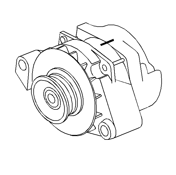
- Connect the drive end frame and rotor assembly to the slip ring end
frame, lining up the marks.
- Install the four through-bolts. Tighten the bolts securely.
- Remove the brush retainer from the end frame.
- Test the generator output. Refer to
Generator Assembly Bench Check
.


