Engine Mount Replacement Right Side
Removal Procedure
Tools Required
| • | J 41044 Engine Support Adapters |
| • | J 42451 Engine Support Adapter Kit |
| • | J 28467-B Universal Support Fixture |
| • | J 36462-A Engine Support Adapter Leg |
Right Side
- Support the engine using the J 42451 ,J 28467-B and the J 36462-A .
- Raise and suitably support the vehicle. Refer to Lifting and Jacking the Vehicle in General Information.
- Remove the starter motor. Refer to Starter Motor Replacement in Engine Electrical.
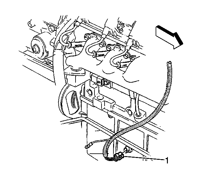
- Disconnect the low oil level sensor electrical connector (1).
- Remove the negative lead bolt (1) and lead (2) from the engine block.
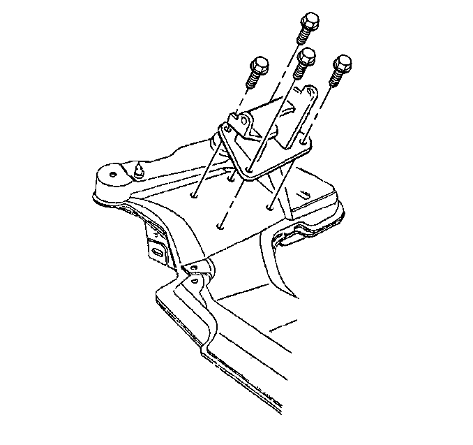
- Remove the engine mount bracket to crossmember bolts.
- Lower the vehicle.
- Raise the right side of the engine with the support fixture.
- Raise and suitably support the vehicle. Refer to Lifting and Jacking the Vehicle in General Information.
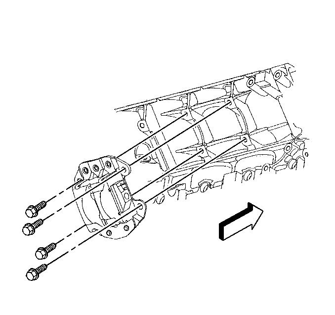
- Remove the engine mount bracket to block bolts.
- Remove the engine mount from the vehicle.
- Separate the upper and lower mount on the bench.
Notice: When raising or supporting the engine for any reason, do not use a jack under the oil pan, any sheet metal, or the crankshaft pulley. Due to the small clearance between the oil pan and the oil pump screen, jacking against the oil pan may cause the pan to be bent against the pump screen. This will result in a damaged oil pickup unit.

Installation Procedure
- Loosely install the upper and lower mount together on the bench.
- Install the engine mount to the vehicle.
- Install the engine mount bracket to block bolts.
- Lower the vehicle.
- Lower the right side of the engine.
- Raise and suitably support the vehicle. Refer to Lifting and Jacking the Vehicle in General Information.
- Install the engine mount bracket to crossmember bolts.
- Tighten the engine mount through bolt and mount nut.
- Install the negative lead (2) and bolt (1) to the engine block.
- Connect the low oil level sensor electrical connector (1).
- Install the starter motor. Refer to Starter Motor Replacement in Engine Electrical.
- Lower the vehicle.

Notice: Use the correct fastener in the correct location. Replacement fasteners must be the correct part number for that application. Fasteners requiring replacement or fasteners requiring the use of thread locking compound or sealant are identified in the service procedure. Do not use paints, lubricants, or corrosion inhibitors on fasteners or fastener joint surfaces unless specified. These coatings affect fastener torque and joint clamping force and may damage the fastener. Use the correct tightening sequence and specifications when installing fasteners in order to avoid damage to parts and systems.
Tighten
Tighten the engine mount bracket to block bolts to 50 N·m
(37 lb ft).

Tighten
Tighten the engine mount bracket to crossmember bolts to 58 N·m
(43 lb ft).
Tighten
| • | Tighten the through bolt to 95 N·m (70 lb ft). |
| • | Tighten the engine mount nut to 80 N·m (59 lb ft). |

Tighten
Tighten the negative lead bolt (1) to the engine block to 32 N·m
(24 lb ft)

Engine Mount Replacement Left Side
Removal Procedure
Tools Required
| • | J 41044 Engine Support Adapters |
| • | J 42451 Engine Support Adapter Kit |
| • | J 28467-B Universal Support Fixture |
| • | J 36462-A Engine Support Adapter Leg |
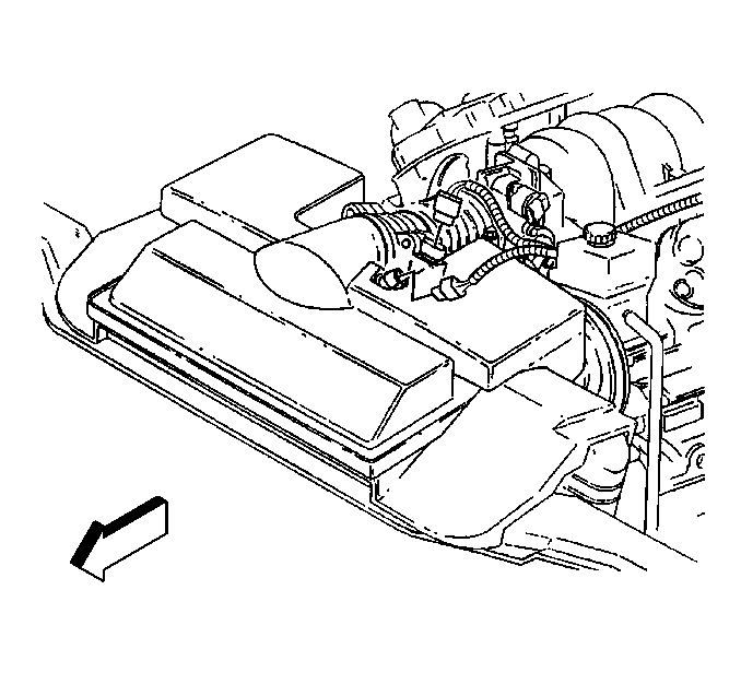
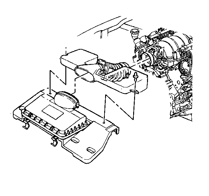
- Disconnect the intake air temperature (IAT) sensor electrical connector at the duct.
- Disconnect the mass airflow (MAF) sensor electrical connector at the duct.
- Remove the air intake duct from the throttle body and the air cleaner box.
- Support the engine using theJ 42451 ,J 28467-B , and the J 36462-A .
- Raise and suitably support the vehicle. Refer to Lifting and Jacking the Vehicle in General Information.
- Remove the left oxidation catalytic converter. Refer to Oxidation Catalytic Converter Replacement in Engine Exhaust.
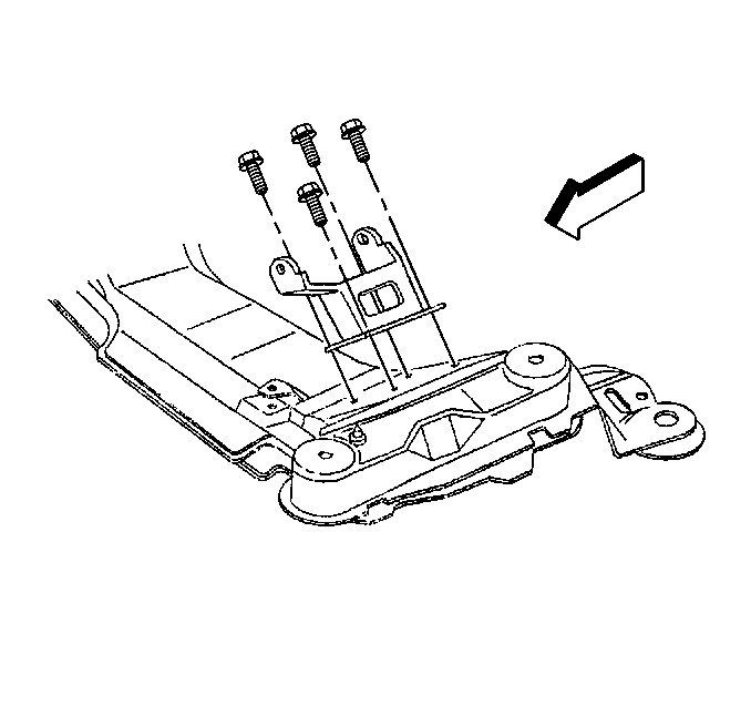
- Remove the engine mount bracket to crossmember bolts.
- Lower the vehicle.
- Raise the left side of the engine with the support fixture.
- Raise and suitably support the vehicle. Refer to Lifting and Jacking the Vehicle in General Information.
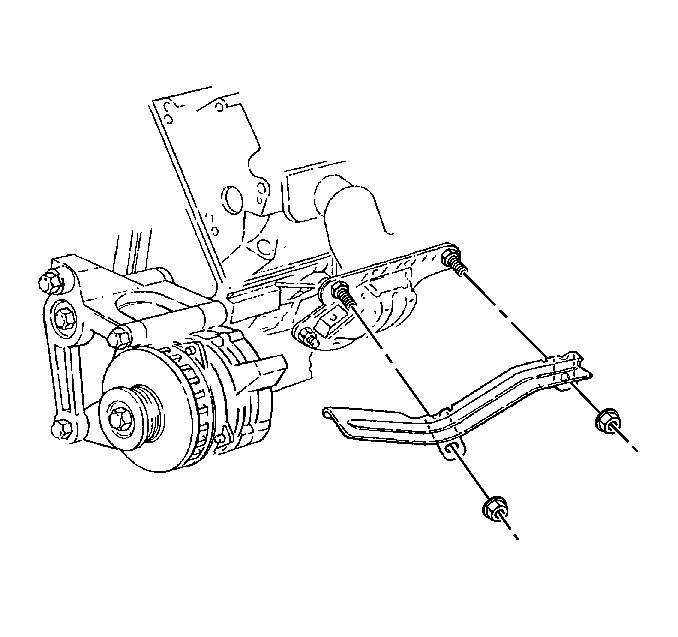
- Remove the engine mount heat shield nuts.
- Remove the engine mount heat shield.
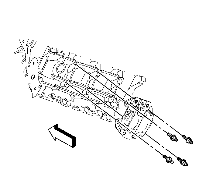
- Remove the engine mount bracket to block studs.
- Remove the engine mount from the vehicle.
- Separate the upper and lower mount on the bench.
Notice: When raising or supporting the engine for any reason, do not use a jack under the oil pan, any sheet metal, or the crankshaft pulley. Due to the small clearance between the oil pan and the oil pump screen, jacking against the oil pan may cause the pan to be bent against the pump screen. This will result in a damaged oil pickup unit.
Installation Procedure
- Loosely install the upper and lower mount together on the bench.
- Install the engine mount to the vehicle.
- Install the engine mount bracket to block studs.
- Install the engine mount heat shield.
- Install the engine mount heat shield nuts.
- Lower the vehicle.
- Lower the right side of the engine.
- Raise and suitably support the vehicle. Refer to Lifting and Jacking the Vehicle in General Information.
- Install the engine mount bracket to crossmember bolts.
- Tighten the engine mount through bolt and mount nut.
- Install the left oxidation catalytic converter. Refer to Oxidation Catalytic Converter Replacement in Engine Exhaust.
- Lower the vehicle.
- Install the air intake duct to the throttle body and the air cleaner box.
- Connect the IAT sensor electrical connector.
- Connect the MAF sensor electrical connector.

Notice: Use the correct fastener in the correct location. Replacement fasteners must be the correct part number for that application. Fasteners requiring replacement or fasteners requiring the use of thread locking compound or sealant are identified in the service procedure. Do not use paints, lubricants, or corrosion inhibitors on fasteners or fastener joint surfaces unless specified. These coatings affect fastener torque and joint clamping force and may damage the fastener. Use the correct tightening sequence and specifications when installing fasteners in order to avoid damage to parts and systems.
Tighten
Tighten the engine mount bracket to block studs to 50 N·m
(37 lb ft).

Tighten
Tighten the engine mount heat shield nuts to 10 N·m (89 lb in).

Tighten
Tighten the engine mount bracket to crossmember bolts to 58 N·m
(43 lb ft).
Tighten
| • | Tighten the through bolt to 95 N·m (70 lb ft). |
| • | Tighten the engine mount nut to 80 N·m (59 lb ft). |


