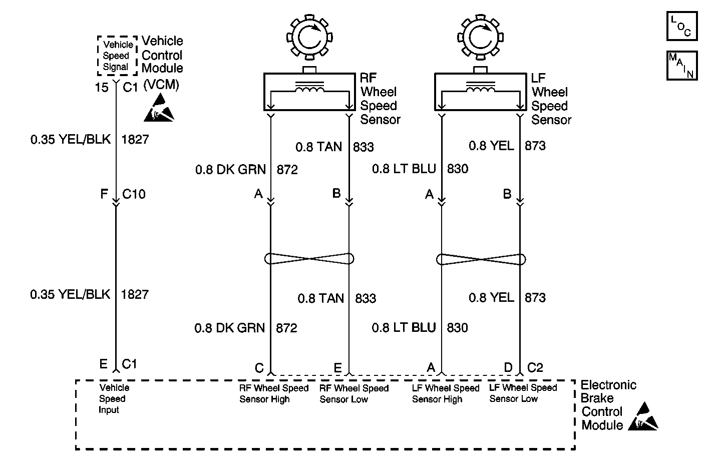
Circuit Description
As a toothed ring passes by the wheel speed sensor, changes in the electromagnetic field cause the wheel speed sensor to produce a sinusoidal (AC) voltage signal. The frequency and amplitude of the sinusoidal (AC) voltage signal are proportional to the wheel speed. The amplitude of the wheel speed signal is directly related to the distance between the wheel speed sensor coil and the toothed ring. This distance is referred to as the air gap. The EBCM can detect wheel speed signal malfunctions as they happen. An error in reported wheel speed can be compensated for by the EBCM up to a point. The error compensation will allow the EBCM to continue to function normally instead of setting a DTC. If the wheel speed mismatch increases beyond that point, the EBCM will set a DTC.
Conditions for Running the DTC
| • | Ignition switch in the RUN position. |
| • | Vehicle speed greater than 40 km/h (25 mph). |
Conditions for Setting the DTC
| • | Any wheel speed differing from the vehicle speed by greater than 10%. |
| • | No unexpected wheel acceleration, or anything that generates consistent differences between the wheel speed signals |
Action Taken When the DTC Sets
| • | The ABS indicator lamp turns on |
| • | The ABS disables |
Malfunction responses to DTC C0238 vary, depending on the affected subsystem.
| • | ABS--Ignition latched |
| • | DRP--DRP critical |
For a detailed explanation of DTC malfunction responses, refer to Self-Diagnostics .
Conditions for Clearing the DTC
| • | Repair the conditions responsible for setting the DTC. |
| • | Use the Clear DTCs function on the Scan Tool |
| • | An Ignition Latched DTC will disable ABS and DRP during the course of the current ignition cycle, (even if the cause of the DTC is intermittent). The DTC will be stored in the EBCM memory until it is repaired, and/or the DTC is cleared. After the DTC is repaired and/or cleared and the ignition is turned to ON, the ABS lamp will remain lit until the EBCM completes a power-up self test. This test concludes when the vehicle has reached a speed of greater than 13 km/h (8 mph) and the wheel speed inputs have been checked by the EBCM. |
Diagnostic Aids
Installing significantly different tires on the vehicle usually sets a DTC C0238. If this condition exists, match the tire size to manufacturer specifications. Refer to Tire Placard . Perform a tire size calibration to ensure that the EBCM calibration matches the installed tire size. Refer to tire size calibration Scan Tool Diagnostics
Step | Action | Value(s) | Yes | No |
|---|---|---|---|---|
1 | Did you perform the ABS Diagnostic System Check? | -- | Go to Step 2 | Go to Diagnostic System Check |
2 | Check the vehicle's tires for four same size tires. Does the vehicle have four same size tires installed? | -- | Go to Step 3 | Go to Step 5 |
3 | Compare the VCM tire calibration with the EBCM tire calibration. Do both tire calibrations match the vehicle installed tire size? | -- | Go to Step 4 | Go to Step 6 |
4 |
Did vehicle operation cause this DTC to set? | -- | Go to Step 7 | Go to Step 10 |
5 | Install correctly matched tires on the vehicle. Did you complete the replacement? | -- | Go to Step 10 | -- |
6 |
Did vehicle operation cause this DTC to set? | -- | Go to Step 9 | Go to Step 10 |
7 | Malfunction is intermittent. Inspect all connectors and harnesses for damage which may result in high resistance when all components are connected. Refer to diagnostic aids for more information. Did you find and repair the condition? | -- | Go to Step 10 | -- |
9 | Replace the Electronic Brake Control Module. Refer to Electronic Brake Control Module Replacement . Did you complete the replacement? | -- | Go to Step 10 | -- |
10 | Operate the vehicle under the conditions for running the DTC as specified in the supporting text. Does the DTC set? | -- | Go to Step 2 | System OK |
