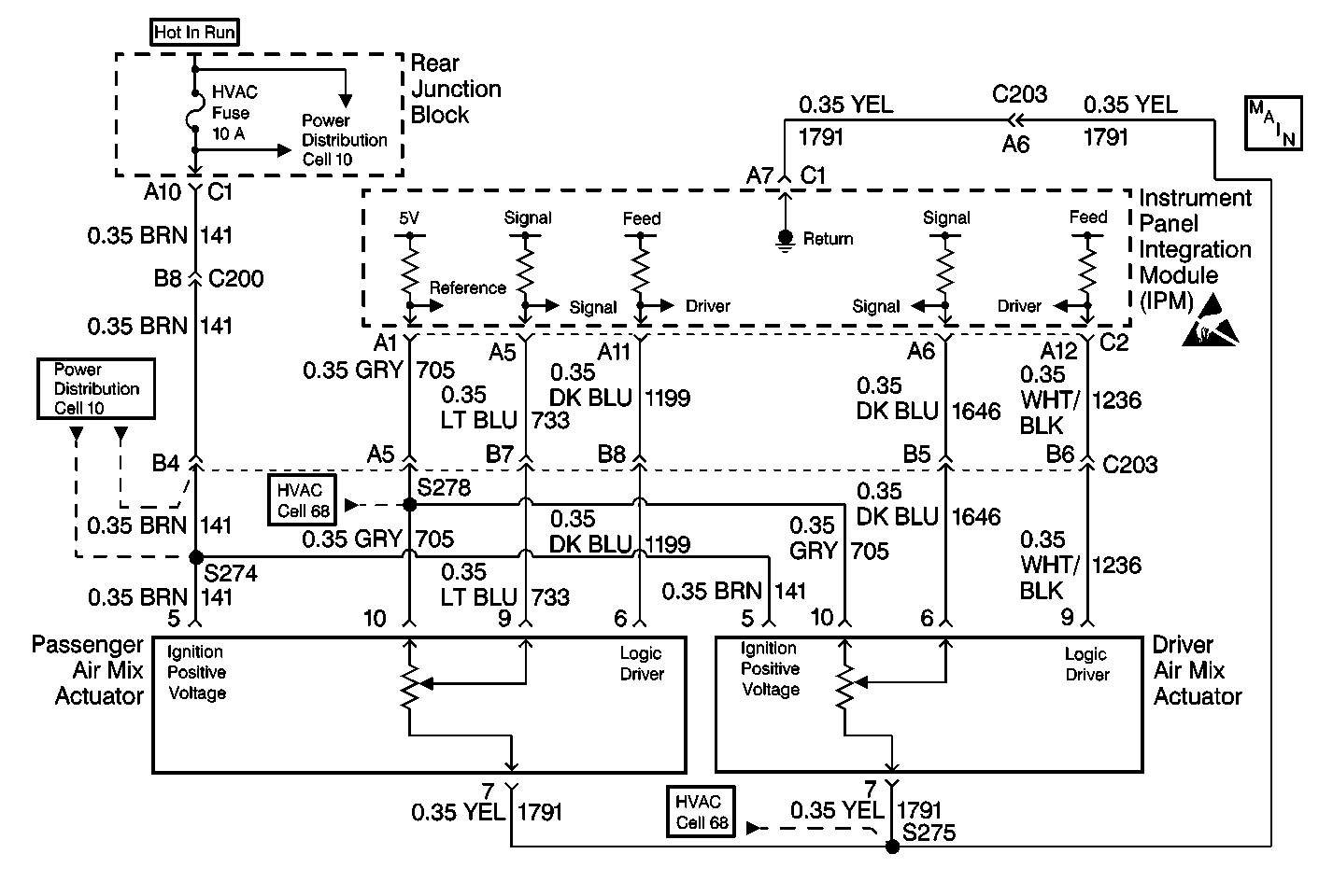
Circuit Description
The rear junction block supplies ignition voltage through circuit 141 (BRN). The IPM commands the actuator to move by suppling voltage on the command line circuit 1199 (DK BLU). The command line voltage and motor actions are as follows:
| • | 0 volts moves toward full hot. |
| • | 2.5 volts stops the motor. |
| • | 5 volts moves toward full cold. |
The IPM determines the current position by monitoring the voltage on the feedback circuit 733 (LT BLU). A feedback potentiometer supplies a regulated 5 volt signal by the IPM on circuit 705 (GRY), and a ground from the IPM circuit 1791 (YEL). The pot is gear driven inside the actuator. The feedback voltage is a function of the motor position with a high voltage of 4-5 volts indicating full hot door position. A low voltage of less then 1 volt indicates the full cold position. Operation of the air mix door actuator can be evaluated through scan tool data.
Conditions for Setting the DTC
| • | Ignition is ON. |
| • | Signal circuit is open or shorted. |
Action Taken When the DTC Sets
| • | A default value of 128 counts will be used by the IPM. |
| • | This default value results in only two positions of the actuator full hot and full cold being used by the system. |
Conditions for Clearing the MIL/DTC
| • | Using a scan tool. |
| • | A current DTC will clear when the diagnostic runs and does not fail. |
| • | IPM battery voltage is interrupted. |
Test Description
The numbers below refer to the step numbers on the diagnostic table.
-
This step determines whether the Body Control Module Diagnostic Symptom Check was performed.
-
This test allows calibration of the actuator by the scan tool.
-
This step determines if the instrument panel integration module (IPM) is malfunctioning.
-
This step determines if the actuator is operational.
Step | Action | Value(s) | Yes | No |
|---|---|---|---|---|
Was the BCM diagnostic system check performed? | -- | Go to Step 2 | ||
Is the difference between minimum and maximum counts within the specified range? | 150-220 counts | Go to Step 3 | Go to Step 4 | |
3 |
Does the system operate normally? | -- | Go to Step 18 | Go to Step 4 |
4 |
Is the voltage measured at the specified value? | 5 V | Go to Step 5 | Go to Step 9 |
5 | Measure voltage at terminal 5, CKT 141 (BRN). Is the voltage measured within the specified value range? | 10 -15 V | Go to Step 6 | Go to Step 9 |
6 | Measure voltage between terminal 5, CKT 141 (BRN) and terminal 7, CKT 1791 (YEL). Is the voltage within the specified value range? | 10 -15 V | Go to Step 7 | Go to Step 9 |
7 |
Is the voltage measured within the specified value? | 0 - 5 V | Go to Step 8 | Go to Step 9 |
8 | Measure voltage at terminal 9, CKT 733 (LT BLU). Is the voltage measured at the specified value? | 5 V | Go to Step 9 | Go to Step 11 |
9 | Inspect the circuits for an open, or short condition. Is an open or short condition present? | -- | Go to Step 10 | Go to Step 11 |
10 | Repair the open or short condition. Is the repair complete? | -- | Go to Step 21 | -- |
View the actuator data on the scan tool. Is the actuator actual data displayed on the scan tool at the specified value? | 5 V or 255 counts | Go to Step 12 | Go to Step 20 | |
12 |
Is voltage present? | -- | Go to Step 13 | Go to Step 20 |
13 |
Is the actuator actual data displayed on the scan tool within the specified value? | 5 V or 255 counts | Go to Step 19 | Go to Step 14 |
Using the scan tool, move the actuator to the hot position and the cold position. Does the actuator move in both directions? | -- | Go to Step 15 | Go to Step 16 | |
15 | Did the actuator actual position feedback change? | -- | Go to Step 21 | Go to Step 19 |
16 | Short terminal 10, CKT 705 (GRY), to terminal 6, CKT 1199 (DK BLU). Did the actuator move? | -- | Go to Step 17 | Go to Step 18 |
17 | Did the actuator actual position feedback change? | -- | Go to Step 21 | Go to Step 19 |
18 | Short terminal 7, CKT 1791 (YEL) to terminal 6, CKT 1199 (DK BLU). Did the actuator move? | -- | Go to Step 17 | Go to Step 19 |
19 | Replace the actuator. Refer to Air Mix Actuator Replacement - Driver in HVAC Systems with A/C-Automatic. Is the repair complete? | -- | Go to Step 21 | -- |
20 | Replace the IPM. Refer to Body Control Module Replacement Heater and A/C Control/IPM. Is the repair complete? | -- | Go to Step 21 | -- |
21 | Confirm proper operation of the A/C system. Does the system operate normally? | -- | -- |
