Exhaust Manifold Replacement Left
Removal Procedure
- Remove the engine mount and bracket. Refer to Engine Mount Replacement .
- Raise and support the vehicle. Refer to Lifting and Jacking the Vehicle in General Information.
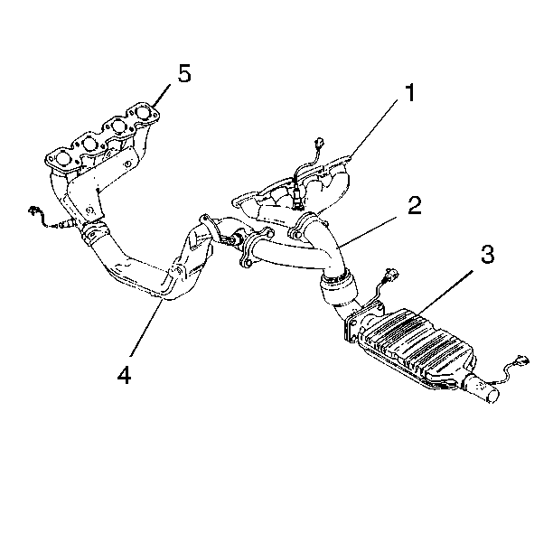
- Remove the two bolts at the manifold outlet flange (4).
- Remove the oxygen sensor if replacement is necessary. Refer to Heated Oxygen Sensor Replacement - Bank 2 in Engine Controls-4.6 L.
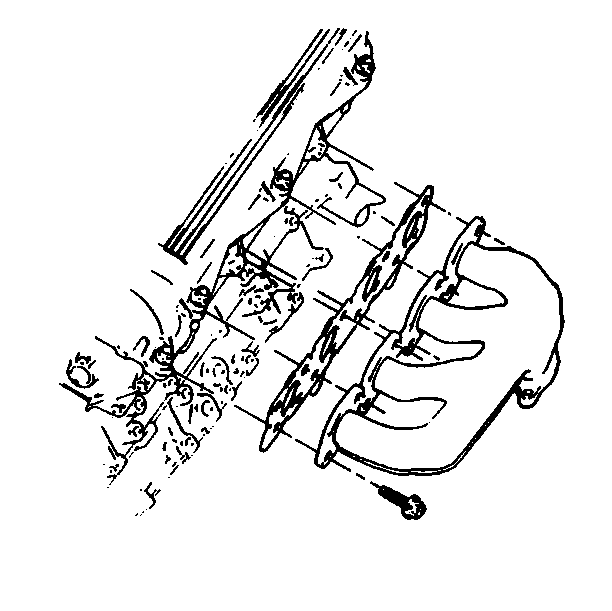
- Remove the exhaust manifold bolts.
- Remove the manifold and the gasket. Discard the gasket.
- Clean and inspect the exhaust manifold. Refer to Exhaust Manifold Cleaning and Inspection .
Installation Procedure
- Install the exhaust manifold by inserting the outlet pipe partially into the exhaust crossover pipe.
- Move the manifold into position.
- Install the new gasket to the manifold. Hold the gasket in position by inserting two bolts.
- Start the remainder of the manifold bolts.
- Install the two bolts at the manifold outlet flange (4).
- Install the oxygen sensor. Refer to Heated Oxygen Sensor Replacement - Bank 2 in Engine Controls-4.6 L.
- Install the engine mount and bracket. Refer to Engine Mount Replacement .
- Lower the vehicle.

Notice: Use the correct fastener in the correct location. Replacement fasteners must be the correct part number for that application. Fasteners requiring replacement or fasteners requiring the use of thread locking compound or sealant are identified in the service procedure. Do not use paints, lubricants, or corrosion inhibitors on fasteners or fastener joint surfaces unless specified. These coatings affect fastener torque and joint clamping force and may damage the fastener. Use the correct tightening sequence and specifications when installing fasteners in order to avoid damage to parts and systems.
Tighten
Tighten the bolts to 25 N·m (18 lb ft).

Tighten
Tighten the bolts to 25 N·m (18 lb ft).
Exhaust Manifold Replacement Right
Removal Procedure
- Remove the oxygen sensor. Refer to Heated Oxygen Sensor Replacement - Bank 1 Sensor 1 in Engine Controls-4.6 L.
- Raise and support the vehicle. Refer to Lifting and Jacking the Vehicle in General Information.
- Remove the exhaust front pipe. Refer to Front Pipe Replacement in Engine Exhaust.
- Disconnect the real time dampening sensor links from the lower control arms.
- Disconnect the intermediate shaft from the steering gear.
- Support the rear cross member of the engine cradle with a tall screw jack.
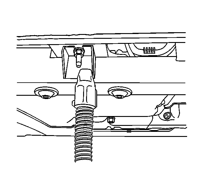
- Remove the four cradle-to-body bolts.
- Lower the rear of the engine cradle.
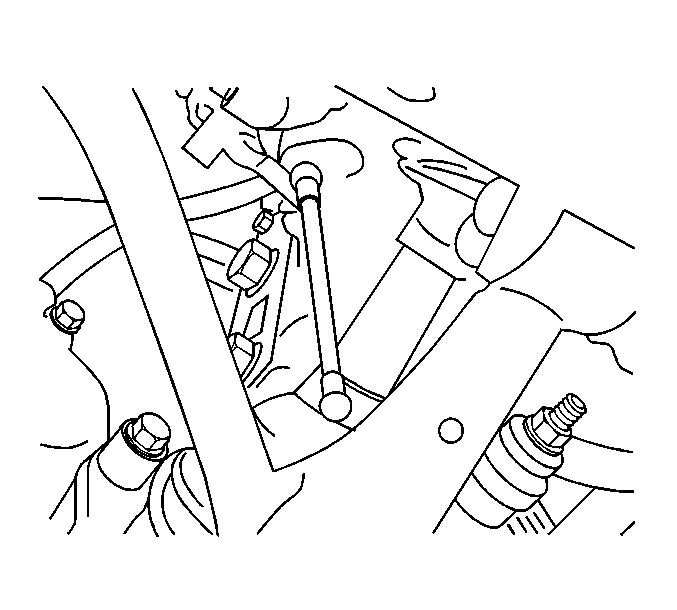
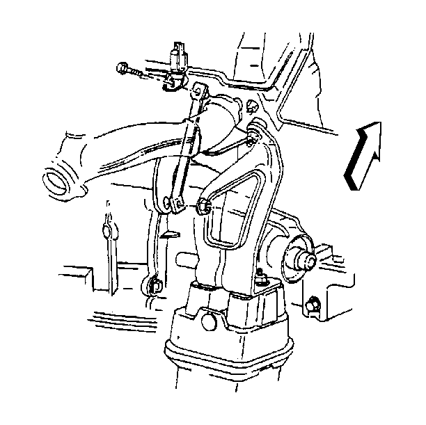
- Remove the right side cylinder head to the transaxle brace.
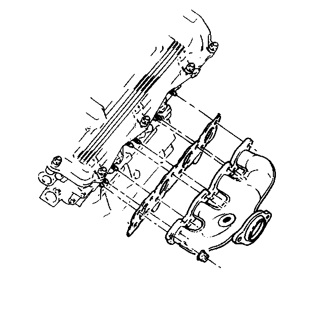
- Remove the exhaust manifold nuts. Some nuts may require removal with an open end wrench or universal coupling tools.
- Remove the manifold (1) and the gasket. Discard the gasket.
- Clean and inspect the exhaust manifold. Refer to Exhaust Manifold Cleaning and Inspection .

Installation Procedure
- Install the new manifold gasket over the cylinder head studs.
- Install the manifold (1) and the nuts.
- Install the right side cylinder head to the transaxle brace.
- Raise the engine cradle into position.
- Remove the screw jack.
- Connect the intermediate shaft to the steering gear.
- Connect the real time dampening sensor links to the lower control arms.
- Install the exhaust front pipe. Refer to Front Pipe Replacement in Engine Exhaust.
- Lower the vehicle.
- Install the oxygen sensor. Refer to Heated Oxygen Sensor Replacement - Bank 1 Sensor 1 in Engine Controls-4.6 L.

Notice: Use the correct fastener in the correct location. Replacement fasteners must be the correct part number for that application. Fasteners requiring replacement or fasteners requiring the use of thread locking compound or sealant are identified in the service procedure. Do not use paints, lubricants, or corrosion inhibitors on fasteners or fastener joint surfaces unless specified. These coatings affect fastener torque and joint clamping force and may damage the fastener. Use the correct tightening sequence and specifications when installing fasteners in order to avoid damage to parts and systems.
Tighten
Tighten the nuts to 25 N·m (18 lb ft).

Tighten
Tighten the bolt and nut to 47 N·m (35 lb ft).

Tighten
Tighten the four bolts to 191 N·m (141 lb ft).
Tighten
Tighten the pinch bolt to 47 N·m (35 lb ft).


