Steering Shaft, Lower Bearing, and Jacket - Disassemble - Off Vehicle Column Shift
Disassembly Procedure
Tools Required
J 23072 Shift Tube Remover
- Remove the shift lever. Refer to
Shift Lever Replacement - On Vehicle
.
- Remove the steering column housing assembly. Refer to
Steering Column Jacket - Disassemble - Off Vehicle
.
- Remove the ignition switch assembly. Refer to
Ignition Switch Assembly - Disassemble - Off Vehicle
.
- Remove the electrical BTSI actuator. Refer to
Automatic Transmission Shift Lock Control Disassemble - Off Vehicle
.
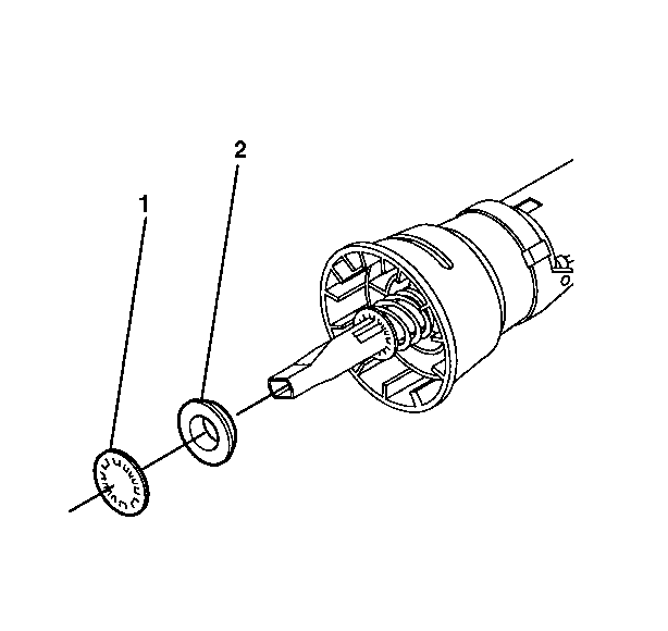
- Remove and dispose of the lower spring
retainer (1).
- Remove the seal retaining bushing (2).
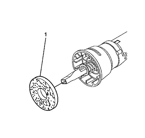
- If no sensor is present, remove the steering
shaft seal (1).
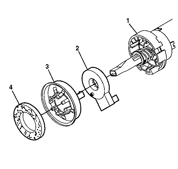
- Perform the following steps if the Hi
Res sensor is present.
| 8.1. | Remove the steering shaft seal (4). |
| 8.2. | Remove the retainer sensor (3). |
| 8.3. | Remove the hi res steering wheel position sensor (2). |
| 8.4. | Remove the sensor adapter (1). |
- The rest of the column with or without the sensor is performed
the same.
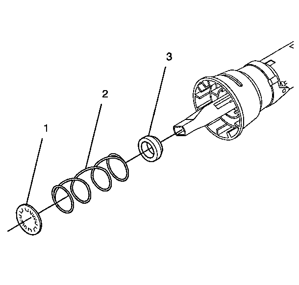
- Remove the lower spring retainer (1).
- Remove the lower bearing spring (2).
- Remove the lower bearing seat (3).
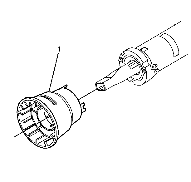
- If no sensor is present, remove the bearing
retainer (1).
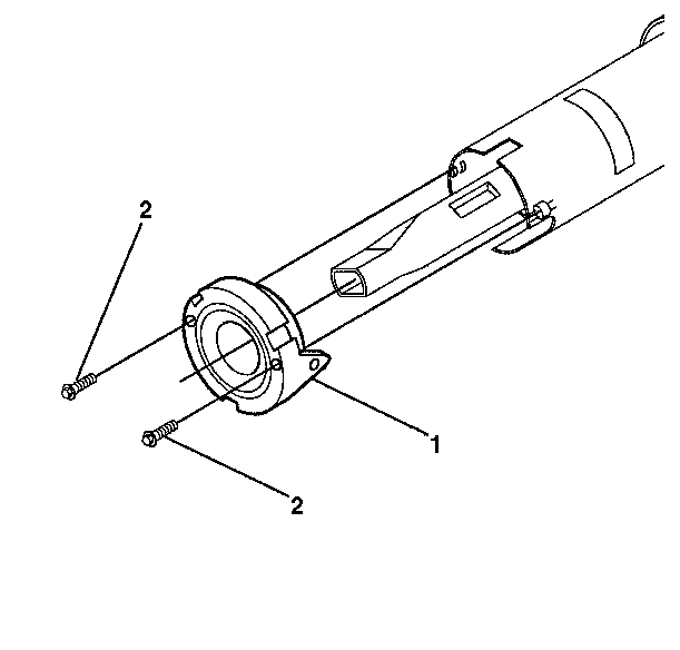
- Remove the 2 hex washer head tapping
screws (2).
- Remove the adapter and bearing assembly (1).
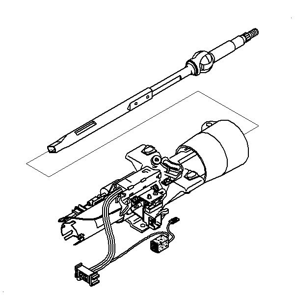
- Remove the steering shaft assembly.

Important: Mark the upper shaft assembly and the steering shaft assembly to ensure
proper assembly. Failure to assemble properly will cause the steering wheel
to be turned 180 degrees.
- Tilt the upper shaft assembly 90 degrees to the steering shaft
assembly and disengage. If necessary, remove and discard the old centering
sphere and spring.
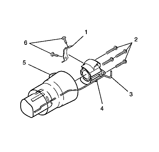
- Remove the 4 torx head screws (2).
- Remove the steering column housing support assembly (4)
with the dimmer switch assembly (3) still connected.
- Remove the 2 oval head cross recess screws (6).
- Remove the shift lever gate (1).
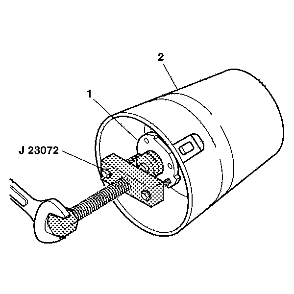
- The shift tube assembly must be in proper
position in the end of the jacket assembly.
- Remove the shift tube assembly (1) using J 23072
.
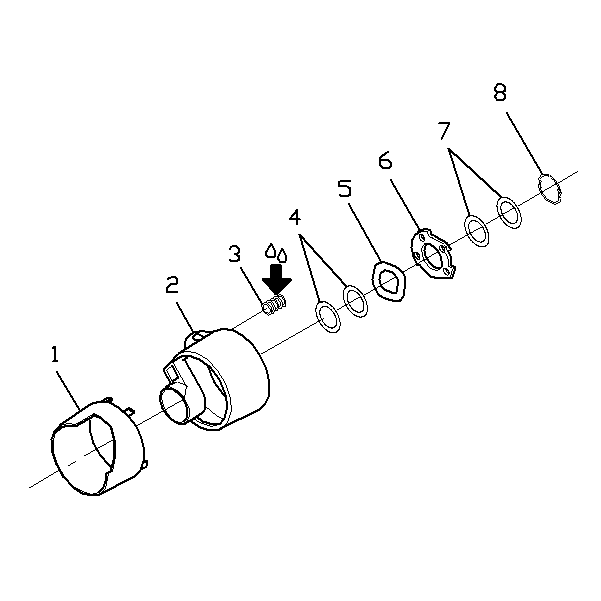
- Remove the shift tube retaining ring (8).
- Remove the 2 thrust washer (7).
- Remove the lock plate (6).
- Remove the wave washer (5).
- Remove the 2 thrust washer (4).
- Remove the shift lever spring (3).
- Remove the gear shift bowl assembly (2).
- Remove the gear shift bowl shroud (1).
Steering Shaft, Lower Bearing, and Jacket - Disassemble - Off Vehicle Floor Shift
Disassembly Procedure
- Remove the hazard knob.
- Remove the steering column housing assembly. Refer to
Steering Column Jacket - Disassemble - Off Vehicle
.
- Remove the ignition switch assembly. Refer to
Ignition Switch Assembly - Disassemble - Off Vehicle
.

- Remove and dispose of
the lower spring retainer (1).
- Remove the seal retaining bushing (2).

- If no sensor is present,
remove the steering shaft seal (1).

- Perform the following
steps if the Hi Res sensor is present.
| 7.1. | Remove the steering shaft seal (4). |
| 7.2. | Remove the retainer sensor (3). |
| 7.3. | Remove the hi res steering wheel position sensor (2). |
| 7.4. | Remove the sensor adapter (1). |
- The rest of the column with or without sensor is the same.

- Remove the lower spring
retainer (1).
- Remove the lower bearing spring (2).
- Remove the lower bearing seat (3).

- If no sensor is present,
remove the bearing retainer (1).

- Remove the 2 hex washer
head tapping screws (2).
- Remove the adapter and bearing assembly (1).

- Remove the steering shaft
assembly.

Important: Mark the upper shaft assembly and the steering shaft assembly to ensure
proper assembly. Failure to assemble properly will cause the steering wheel
to be turned 180 degrees.
- Tilt the upper shaft assembly 90 degrees to the steering shaft
assembly and disengage. If necessary, remove and discard the old centering
sphere and spring.
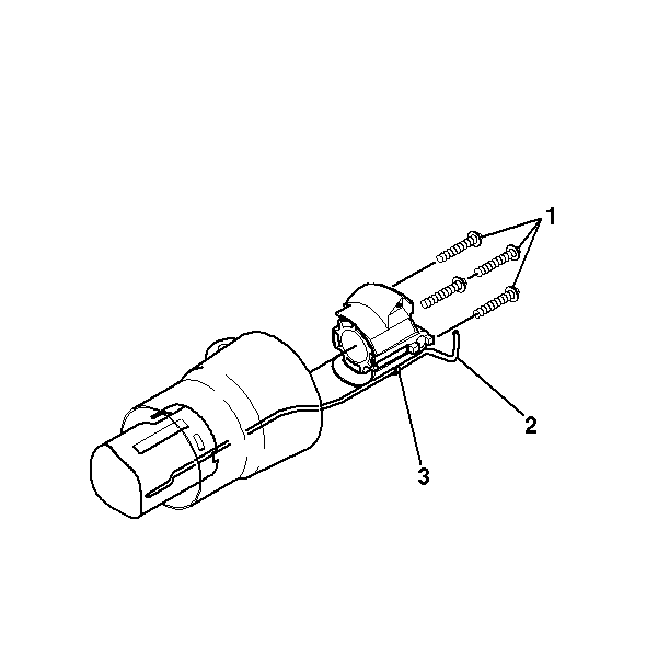
- Remove the 4 hex
washer head tapping screws (1).
- Remove the steering column housing support assembly (3)
with the dimmer switch rod (2) still connected.


