Tools Required
| • | J 28467-B Universal Engine Support Fixture |
| • | J 35551 Ball Stud Nut Wrench |
| • | J 41160 Transmission Jack Adapter |
Removal Procedure
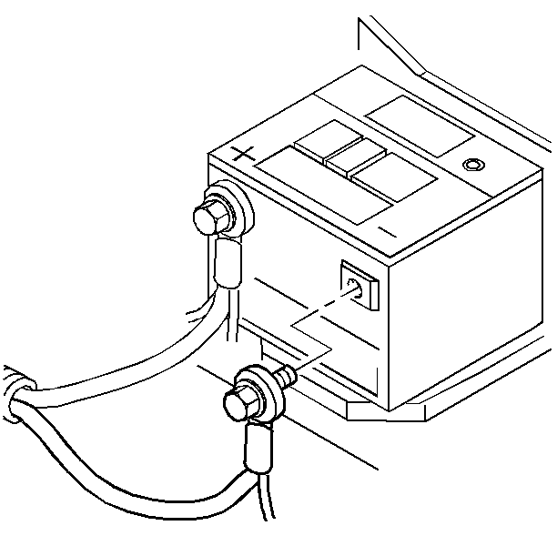
- Disconnect the battery negative cable assembly from the battery negative terminal.
- Remove the headlamp housing upper filler panel. Refer to Filler Panel Replacement - Upper in Body Front End.
- Remove the diagonal brace. Refer to Cross Vehicle Brace Replacement in Body Front End.
- Remove the air cleaner assembly. Refer to Air Cleaner Assembly Replacement in Engine Controls.
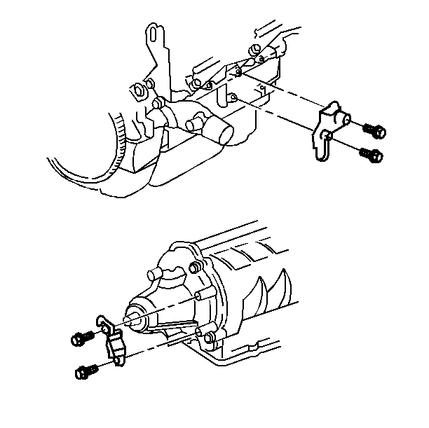
- Remove the shift control cable and the bracket at the transmission.
- Remove the torque struts.
- Remove the oil cooler lines at the cooler and the oil sending line at the transmission.
- Remove the two upper bell housing bolts.
- Remove the power steering return hose at the auxiliary cooler.
- Install plugs in the cooler and the return hose to prevent fluid leakage or contamination.
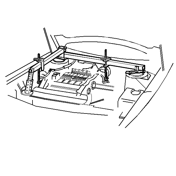
- Install theJ 28467-B .
- Raise the left side of the powertrain (the transmission side) 25.4 mm (I.0 in) above the powertrain resting position with the adjusting screws.
- Raise the vehicle. Refer to Lifting and Jacking the Vehicle in General Information.
- Support the vehicle with safety stands.
- Remove both front tires and wheels. Refer to Tire and Wheel Removal and Installation in Suspension.
- Remove both front wheel opening splash shields. Refer to Front Bumper Fascia Extension Replacement in Body Front End.
- Remove both front suspension position sensors from the lower control arms and position out of the way.
- Remove both stabilizer links from the struts. Refer to Stabilizer Shaft Link Replacement in Suspension.
- Remove both tie rod cotter pins and nuts and separate both tie rods from the steering knuckles. Refer to Rack and Pinion Outer Tie Rod End Replacement in Steering.
- Remove both lower ball joint cotter pins and nuts. Separate both ball joints from the struts. Refer to Lower Control Arm Ball Joint Replacement with V4U/B9Q or without V4U/B9Q in Suspension.
- Remove both drive axles. Refer to Wheel Drive Shaft Replacement in Wheel Drive Shafts.
- Remove the fuel filter bracket from the frame.
- Remove the ABS modulator from the bracket and the support.
- Remove the engine oil pan to transmission bracket.
- Remove the torque converter cover. Refer to Torque Converter Cover Replacement .
- Remove the flywheel to converter bolts.
- Remove the powertrain mount nuts from the frame.
- Remove the clamp bolt (Rotate the steering intermediate shaft so that the steering gear stub shaft clamp bolt is accessible from the left wheel opening).
- Remove the steering intermediate shaft from the steering gear. Refer to Steering Gear Replacement in Steering.
- Remove the electrical harness and connector from the front of the frame.
- Support the rear of frame with an adjustable jack stand.
- Remove the four rear frame bolts.
- Lower the jack stand a few inches to gain access to the power steering gear heat shield and the return line fitting.
- Remove the power steering gear heat shield and the power steering return line at the gear. Install plugs in the steering gear and pressure line in order to prevent fluid leakage or contamination. Refer to Power Steering Hoses Replacement in Power Steering Systems.
- Remove the power steering electrical connector.
- Raise the jack stand and reinstall one rear frame bolt on each side finger tight in order to support the frame.
- Remove the jack stand.
- Remove the support frame.
- Remove the six frame mount bolts.
- Remove the lower frame and/or raise the vehicle with the steering gear attached.
- Remove the following electrical connectors:
- Remove the fuel line bundle from the transmission.
- Remove the left transmission mount and bracket from the transmission.
- Remove the right transmission bracket, the mount, and the brace.
- Remove the engine to transmission heat shield and the bracket.
- Support the transaxle using the J 41160 and a suitable transmission jack.
- Secure the J 41160 to the transaxle.
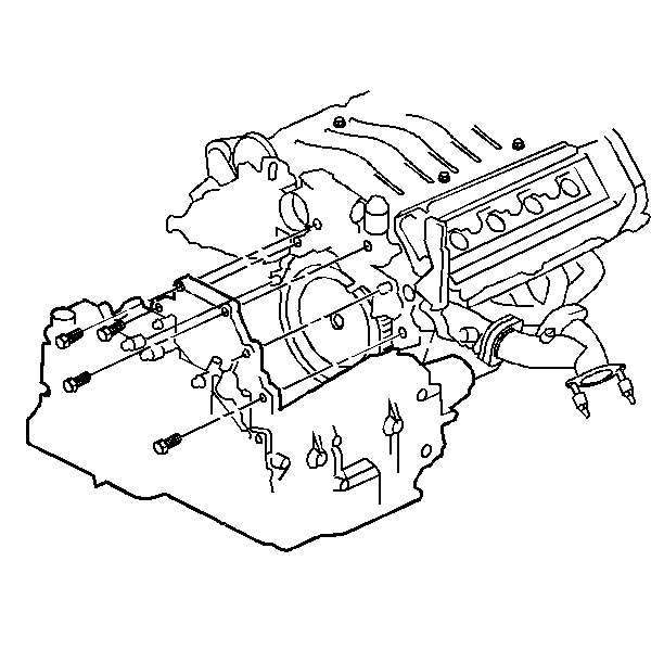
- Remove the engine to transmission bolts.
- Lower the transmission.
- Flush the transmission oil cooler and pipes. Refer to Transmission Fluid Cooler Flushing and Flow Test .
- Remove the manual shaft linkage and the park/neutral position switch.
- Remove the vehicle speed sensor. Refer to Vehicle Speed Sensor Replacement .
- Remove the oil return pipe.
Caution: Unless directed otherwise, the ignition and start switch must be in the OFF or LOCK position, and all electrical loads must be OFF before servicing any electrical component. Disconnect the negative battery cable to prevent an electrical spark should a tool or equipment come in contact with an exposed electrical terminal. Failure to follow these precautions may result in personal injury and/or damage to the vehicle or its components.

Important : Load the support fixture by tightening the wing nuts several turns in order to take the weight of the powertrain off of the mounts and the frame.

Important: Mark the flywheel to converter position so that they can be assembled in the same position.
Caution: Failure to disconnect the intermediate shaft from the rack and pinion steering gear stub shaft can result in damage to the steering gear or to the intermediate shaft. This damage may cause loss of steering control, which could result in an accident and possible personal injury.
Notice: Do not rotate the steering wheel or move the position of the steering gear once the intermediate shaft is disconnected. This will uncenter the Inflatable Restraint coil in the steering column. If the Inflatable Restraint coil becomes uncentered, it may be damaged during vehicle operation.
| • | Three transmission connectors |
| • | VSS connector |


Installation Procedure
- Install the oil return pipe.
- Install the vehicle Speed Sensor. Refer to Vehicle Speed Sensor Replacement .
- Install the park/neutral position switch and the manual shaft linkage.
- Tighten the park/neutral position switch bolts to 12 N·m (106 Ib in).
- Tighten the manual shaft nut to 20 N·m (15 Ib ft).
- Raise the transaxle into position.
- Install the engine to transmission bolts.
- Install the engine to transmission bracket and heat shield.
- Remove the transmission jack and the J 41160 .
- Install the right transmission bracket, mount, and brace.
- Install the left transmission bracket and mount to the transmission.
- Install the fuel line bundle to the transmission.
- Install the following electrical connectors:
- Raise the frame and/or lower the vehicle while locating the engine and transmission mount studs into the frame, harnesses at the frame, and the frame mount bolt holes to the underbody.
- Install two front and two rear frame bolts finger tight in order to support the frame.
- Remove the frame support fixture.
- Support the rear of the frame with an adjustable jack stand.
- Remove two rear frame bolts.
- Lower the jack stand a few inches in order to gain access to the power steering gear.
- Install the power steering pressure hose at the steering gear. Power Steering Hoses Replacement in Power Steering Systems.
- Install the power steering gear electrical connector and power steering gear heat shield:
- Raise the jack stand.
- Install the six frame mount bolts in the following order:
- Install the electrical harness to the front of the frame.
- Install the steering intermediate shaft to the steering gear and install the clamp bolt.
- Install the left and right transmission mount nuts and the right engine mount nuts at the frame.
- Install the fuel filter bracket to the frame.
- Install the flywheel to converter bolts.
- Install both tie rods. Refer to Rack and Pinion Outer Tie Rod End Replacement
- Install torque converter cover. Refer to Torque Converter Cover Replacement .
- Install the engine oil pan to transmission bracket.
- Install the ABS modulator to the bracket.
- Install both drive axles into the transmission. Refer to Wheel Drive Shaft Replacement in Wheel Driveshafts.
- Install both lower ball joint cotter pins and nuts. Refer to Lower Control Arm Ball Joint Replacement with V4U/B9Q or without V4U/B9Q in Suspension.
- Install both tie rods into the steering knuckles and both tie rod nuts and cotter pins. Refer to Rack and Pinion Outer Tie Rod End Replacement in Steering.
- Install both stabilizer links to struts. Refer to Stabilizer Shaft Link Replacement in Suspension.
- Install both front suspension position sensors to the lower control arms.
- Install both front wheel opening splash shields. Refer to Front Bumper Fascia Extension Replacement in Body Front End.
- Install both front tire and wheel assemblies. Refer to Tire and Wheel Removal and Installation in Suspension.
- Lower the vehicle.
- Remove the J 28467-B Universal Engine Support Fixture.
- Install the power steering hose at the auxiliary cooler.
- Install the upper bell housing bolts.
- Install the transmission cooler pipe fittings at the transmission. Install the fittings finger tight.
- Install the oil sending pipe to the transmission.
- Install the torque struts.
- Adjust the park/neutral position switch. Refer to Park/Neutral Position Switch Replacement .
- Install the range control cable and bracket at the transmission.
- Adjust the shift control cable. Refer to Shift Cable Replacement .
- Install the air cleaner assembly. Refer to Air Cleaner Assembly Replacement in Engine Controls.
- Install the headlamp housing upper filler panel. Refer to Filler Panel Replacement - Upper in Body Front End.
- Install the diagonal Brace. Refer to Radiator Support Diagonal Brace Replacement
- Connect the battery negative cable assembly to the battery negative terminal.
- Bleed the power steering system. Refer to Power Steering Gear and Pump in Suspension.
- Add DEXRON-III transmission fluid as required. Refer to Transmission Fluid Filter Replacement and to Fluid Capacity Specifications .
- Check the front suspension alignment, adjust the toe as necessary.
- Reset the transmission adapts. Refer to Electronic Component Description .
- Reset the transmission oil life indicator. Refer to Electronic Component Description .
Notice: Use the correct fastener in the correct location. Replacement fasteners must be the correct part number for that application. Fasteners requiring replacement or fasteners requiring the use of thread locking compound or sealant are identified in the service procedure. Do not use paints, lubricants, or corrosion inhibitors on fasteners or fastener joint surfaces unless specified. These coatings affect fastener torque and joint clamping force and may damage the fastener. Use the correct tightening sequence and specifications when installing fasteners in order to avoid damage to parts and systems.
Tighten

Tighten
Tighten the bolts to 75 N·m (55 Ib ft).
Tighten
Tighten the bolts to 47 N·m (35 Ib ft).

Tighten
Tighten the bolts to 47 N·m (35 Ib ft).
Tighten
Tighten the bolts to 47 N·m (35 Ib ft).
| • | The transmission connectors. |
| • | The VSS connector. |
| • | The ground. |
| • | The transmission harness in order to Install the transmission clip. |
Tighten
Tighten the fitting to 27 N·m (20 Ib ft).
| • | The ground. |
| • | The transmission harness to the transmission clip. |
| 21.1. | Left side #2 mount bolt into the body. |
| 21.2. | Left side #1 mount bolt into the body. |
| 21.3. | The remaining frame mount bolts. |
Notice: Do not rotate the steering wheel or move the position of the steering gear once the intermediate shaft is disconnected. This will uncenter the Inflatable Restraint coil in the steering column. If the Inflatable Restraint coil becomes uncentered, it may be damaged during vehicle operation.
Tighten
Tighten the bolts to 47 N·m (35 Ib ft).
Tighten
Tighten the nuts to 47 N·m (35 Ib ft).
Important: Line up the flywheel and converter using the marks you made at disassembly.
Tighten
Tighten the bolts to 60 N·m (44 Ib ft).
in Steering.
Tighten
Tighten the bolts to 47 N·m (35 Ib ft).
Tighten
Tighten the cooler pipe fittings at transmission to 22 N·m (16 Ib ft).
Tighten
Tighten the bracket bolts to 12 N·m (106 Ib in).

Tighten
Tighten the terminal bolt to 15 N·m (11 lb ft).
