Removal Procedure
Notice: The BCM electrical connectors are designed with tabs and slots that allow the connectors to only fit one way. The connectors do not require excessive force if being installed correctly. Installing the connectors with the wrong mating half or upside down can cause damage to the connector, the BCM, or other vehicle components or systems.
- Turn the ignition switch to the OFF position.
- Disconnect the negative battery cable. Refer to
- Remove the upper center pillar trim. Refer to Center Pillar Upper Trim Panel Replacement in Interior Trim.
- Remove the passenger seat track trim.
- Remove the carpet retainer. Refer to Carpet Retainer Replacement in Interior Trim.
- Remove the right hinge pillar trim finish panel. Refer to Body Hinge Pillar Trim Panel Replacement in Interior Trim.
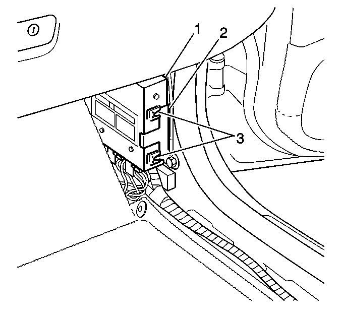
- Gently separate the retainer (2) from the BCM (1).
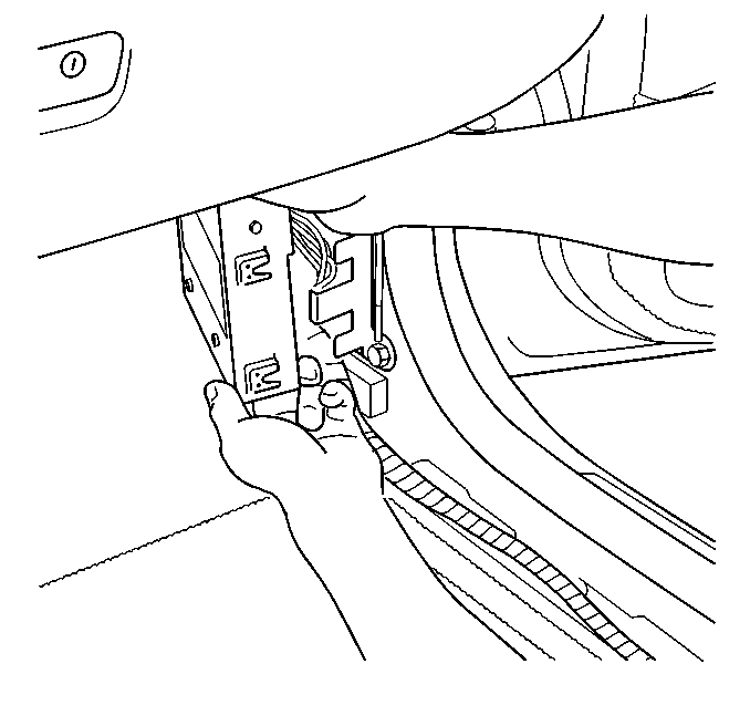
- Slide the BCM (1) out of the guides (3).
- Unclip the antenna wire from the mount slot.
- Remove the BCM from the mounting position.
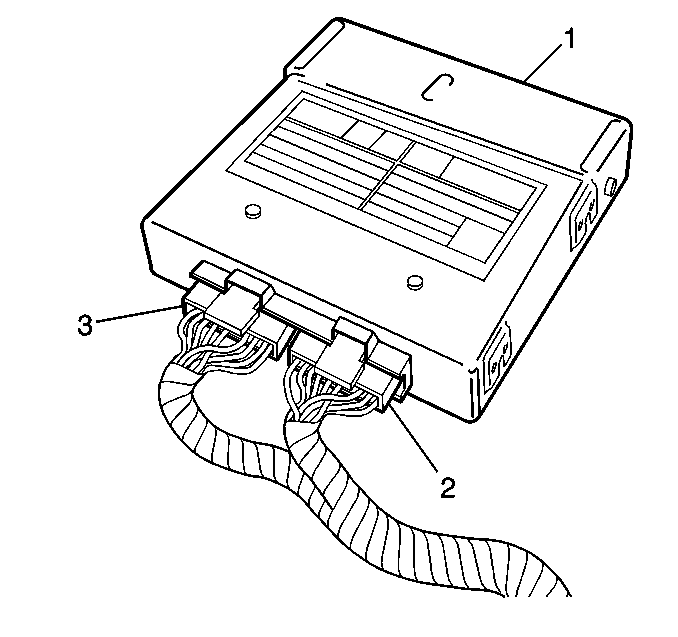
- Remove the harness connectors (2 and 3) from the BCM (1).

Caution: Unless directed otherwise, the ignition and start switch must be in the OFF or LOCK position, and all electrical loads must be OFF before servicing any electrical component. Disconnect the negative battery cable to prevent an electrical spark should a tool or equipment come in contact with an exposed electrical terminal. Failure to follow these precautions may result in personal injury and/or damage to the vehicle or its components.


Installation Procedure
- Install the harness connectors (2 and 3) to the BCM (1).
- Clip the antenna wire to the mount slot.
- Install the BCM into the mounting position.
- Gently seat near end of the BCM (1) into the guides (3).
- Ensure the retainer (2) clips over the edge of the BCM (1) for full BCM installation.
- Install the right hinge pillar trim finish panel. Refer to Body Hinge Pillar Trim Panel Replacement in Interior Trim.
- Install the carpet retainer. Refer to Carpet Retainer Replacement in Interior Trim.
- Install the passenger seat track trim.
- Install the lower center pillar trim. Refer to Center Pillar Upper Trim Panel Replacement in Interior Trim.
- Reconnect the negative battery cable Refer to Battery Negative Cable Disconnection and Connection in Engine Electrical.
- Using the scan tool, select from the Special Functions menu, SETUP NEW BODY CONTROL MODULE. Follow the instructions on the display screen.


