Tools Required
J 41416 Ultrasonic
Leak Detector
Description
The fuel tank assembly consists of an inner fuel tank, evaporative emission
(EVAP) canister, ORVR system and the associated plumbing all encased within
an outer fuel tank housing. The outer housing contains a tube that
allows air between the inner tank and the outer housing to vent. A
leak in any of the internal components of the fuel tank assembly will
exit this vent. The vent is located in front of the fuel tank above
the fuel filter. If a leak is detected by air exiting this vent while
the EVAP system is pressurized, the fuel tank assembly will require
replacement. The internal components of the fuel tank assembly are
not serviceable. A similar vent for the fuel tank pressure sensor is also
located in front of the fuel tank. A leak from this vent while the
EVAP system is pressurized indicates the fuel tank pressure sensor
is leaking.
Important: Before attempting the Fuel Tank Leak Check, place a dry chemical, Class
B, fire extinguisher near the work area.
- Remove the fuel tank. Refer to
Fuel Tank and Evaporation Emission Canister Replacement
.

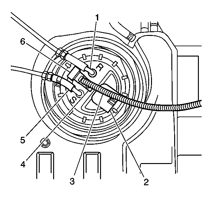
- Plug the following connections:
| • | Fuel feed line connection (5) |
- Install the fuel tank cap.
- Continuously pressurize the fuel tank at the fuel sender return
connection (1) with compressed air regulated to 7-10 kPa (1-1 1/2 psi).
- Test for leaks with the J 41416
. Test the following areas and repair or replace as necessary:
| • | Fuel tank outer housing vent hose |
| • | Fuel tank pressure (FTP) sensor vent hose |
| • | EVAP connections and lines |
| • | Fuel filler cap and neck |
| • | Fuel sender assembly O-ring |

