Tools Required
| • | J 36660-A Torque Angle Meter |
| • | J 42098 Crank Hub TORX® Socket |
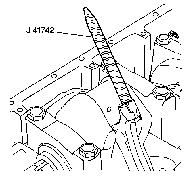
| • | J 41742 Connecting Rod Guide |
Removal Procedure
- Remove the engine oil baffle. Refer to Oil Baffle Replacement .
- Remove the spark plug(s) from the cylinder(s) that is being serviced. Refer to Spark Plug Replacement in Engine Controls - 3.0L (L81).
- Use the J 42098 to rotate the crankshaft.
- Position the connecting rod that is being serviced to bottom dead center (BDC).
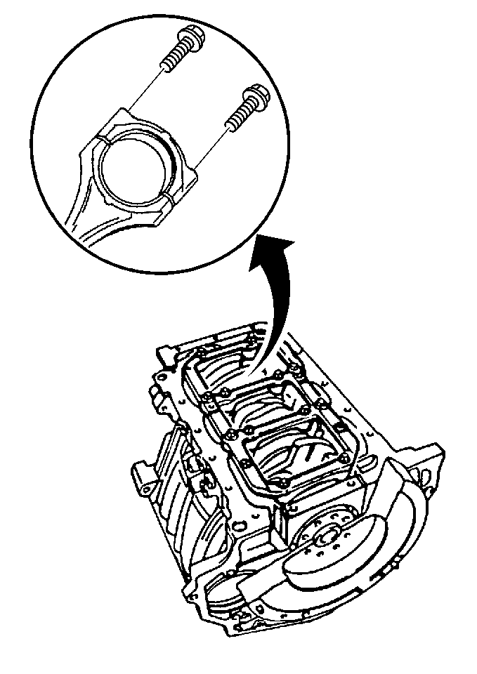
- Remove the connecting rod cap bolts.
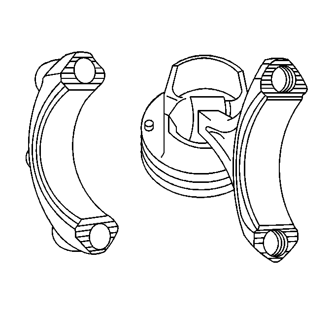
- Remove the connecting rod cap and the lower connecting rod bearing.
- Install a strip of plastic thread to the connecting rod journal.
- Install the connecting rod cap with the connecting rod bearing to the connecting rod.
- The connecting rod bolts can be reused for checking the connecting rod bearing clearance.
- Use the J 36660-A to rotate the connecting rod bolts in the following sequence:
- On the first pass rotate the connecting rod cap bolts to 45 degrees.
- On the second pass (final pass) rotate the connecting rod cap bolts to 45 degrees.
- Remove the connecting rod bolts and the connecting rod bearing cap.
- Compare the width of the flattened plastic thread with the scale on the plastic gage package. Permissible connecting rod bearing clearance is 0.010-0.061 mm (0.0004- 0.0024 in) clearance.
- Install the J 41742 to the connecting rod.
- Use the J 41742 to push up the connecting rod and the piston to access the upper connecting rod bearing.
- Remove the upper connecting rod bearing.

Notice: The mating surfaces of the connecting rods and the connecting rod bearing caps form an individual fit and as a result must not be damaged or replaced under any circumstances. To avoid damage, do not lay the connecting rod bearing caps on the connecting rod bearing mating surface.
Important: Clean the connecting rod journal and the connecting rod bearing shell and lubricate slightly with clean engine oil. This is necessary to prevent the plastic thread of the plastic gage from tearing when the connecting rod cap is removed.
Notice: Use the correct fastener in the correct location. Replacement fasteners must be the correct part number for that application. Fasteners requiring replacement or fasteners requiring the use of thread locking compound or sealant are identified in the service procedure. Do not use paints, lubricants, or corrosion inhibitors on fasteners or fastener joint surfaces unless specified. These coatings affect fastener torque and joint clamping force and may damage the fastener. Use the correct tightening sequence and specifications when installing fasteners in order to avoid damage to parts and systems.
Install the connecting rod cap bolts to the connecting rods.
Tighten
Tighten the connecting rod cap bolts to 35 N·m (26 lb ft).
Tighten

Installation Procedure
- Lubricate the connecting rod bearing journals with clean engine oil.
- Install the upper connecting rod bearing.
- Use the J 41742 to pull down the connecting rod and the piston to the crankshaft journal.
- Remove the J 41742 from the connecting rod.
- Install the connecting rod cap with the connecting rod bearing to the connecting rod.
- Install the new connecting rod cap bolts to the connecting rods.
- Use the J 36660-A to rotate the connecting rod bolts in the following sequence:
- On the first pass rotate the connecting rod cap bolts to 45 degrees.
- On the second pass (final pass) rotate the connecting rod cap bolts to 45 degrees.
- Install the spark plug(s) to the cylinder(s) that was serviced. Refer to Spark Plug Replacement in Engine Controls - 3.0L (L81).
- Install the engine oil baffle. Refer to Oil Baffle Replacement .

Notice: Do not scrape, shim, or file bearing inserts. If the bearing surface of the insert is touched with bare fingers, the skin oil and acids will etch the bearing surface.
Important: Make sure that the connecting rod cap bolt holes and the connecting rod cap mating surfaces are clean and dry.


Tighten
Tighten the connecting rod cap bolts to 35 N·m (26 lb ft).
Tighten
