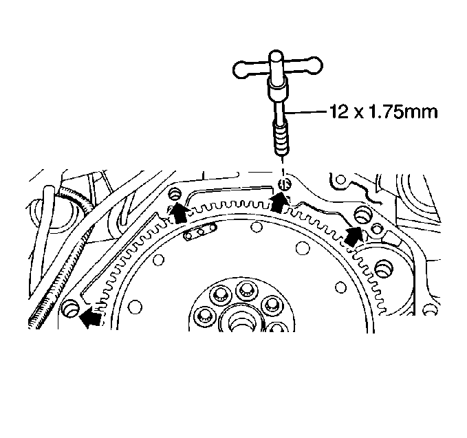
Notice: Automatic transmission oil cooler flushing must be performed when an
automatic transmission is removed for service. The flushing procedure should
be performed after the installation of the overhauled or replacement
transmission. Failure to flush the system may cause damage to the system and
its components.
- Flush the transmission oil cooler. Refer to
Transmission Fluid Cooler Flushing and Flow Test
.
- Install the transmission.
- Apply thread locking compound P/N 12345382 to the transmission
housing to engine bolt threads.
Notice: Use the correct fastener in the correct location. Replacement fasteners
must be the correct part number for that application. Fasteners requiring
replacement or fasteners requiring the use of thread locking compound or sealant
are identified in the service procedure. Do not use paints, lubricants, or
corrosion inhibitors on fasteners or fastener joint surfaces unless specified.
These coatings affect fastener torque and joint clamping force and may damage
the fastener. Use the correct tightening sequence and specifications when
installing fasteners in order to avoid damage to parts and systems.
- Install the transmission
housing to engine bolts.
Tighten
Tighten the transmission housing to engine block bolts to 60 N·m
(44 lb ft).
- Test the torque converter for freedom of rotation.
| • | The torque converter must rotate freely. |
| • | If not, the torque converter is not fully seated in the pump drive
gear. Perform the following: |
| 1. | Remove the transmission. |
| 2. | Inspect the transmission pump gears for damage, repair as needed. |
| 3. | Install the torque converter. The torque converter must be fully
seated. |
| 4. | Install the transmission. |
- Remove the support from the front of the engine.
- Connect the electrical connectors at the following locations:
| • | The transmission control selector switch |
| • | The transmission adapter case |
| • | The transmission main case |
| • | The transmission speed sensor |
| • | Attach the harness clip to the housing |
- Install the transmission vent hose.
- Raise the transmission into position.
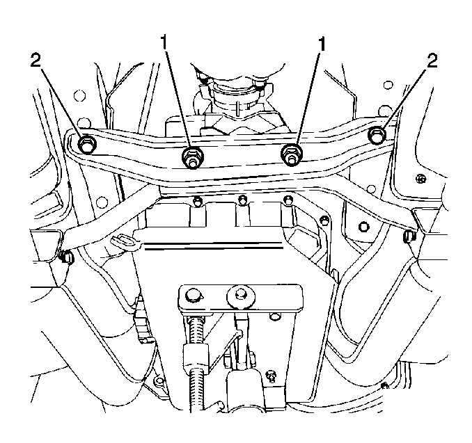
- Install the crossmember.
- Install the 2 crossmember to body bolts (2).
Tighten
Tighten the crossmember to body bolts to 45 N·m (33 lb ft).
- Install the 2 crossmember to transmission mount nuts (1).
Tighten
Tighten the transmission mount nuts to 20 N·m (15 lb ft).
- Remove the transmission support.
- Apply thread locking compound P/N 12345382 to the transmission
housing to engine oil pan bolts.
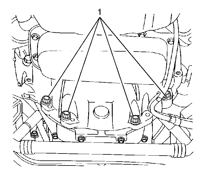
- Install the transmission
housing to engine oil pan bolts (1).
Tighten
Tighten the transmission housing to engine oil pan bolts to 40 N·m
(30 lb ft).
- Install the exhaust catalytic converters. Refer to
Catalytic Converter Replacement
.
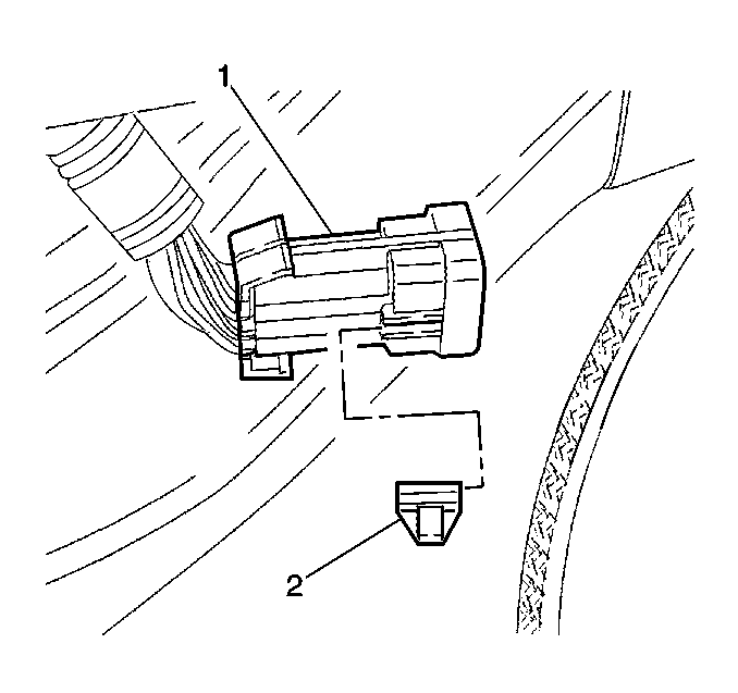
- Connect the oxygen sensor
connectors (1).
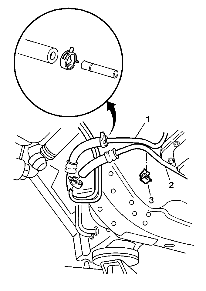
- Install the transmission
oil cooler inlet (1) and outlet (2) pipes.
| • | Connect the hoses on the pipes. |
| • | Slide the clamps toward the hose connection. |
Important: Install and only finger tighten all 6 flywheel to torque converter bolts.
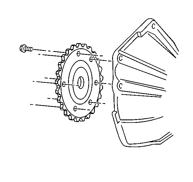
- Install the new flywheel
to torque converter bolts:
| • | Remove the retaining compound from the first three threads of
the new flywheel to torque converter bolts. |
| • | Observe the marks made during disassembly and align in original
position. |
| • | Ensure weld nuts on torque converter are flush with flywheel. |
| • | Tighten the torque converter bolts. |
Tighten
Tighten the flywheel to torque converter bolts to 30 N·m
(22 lb ft).
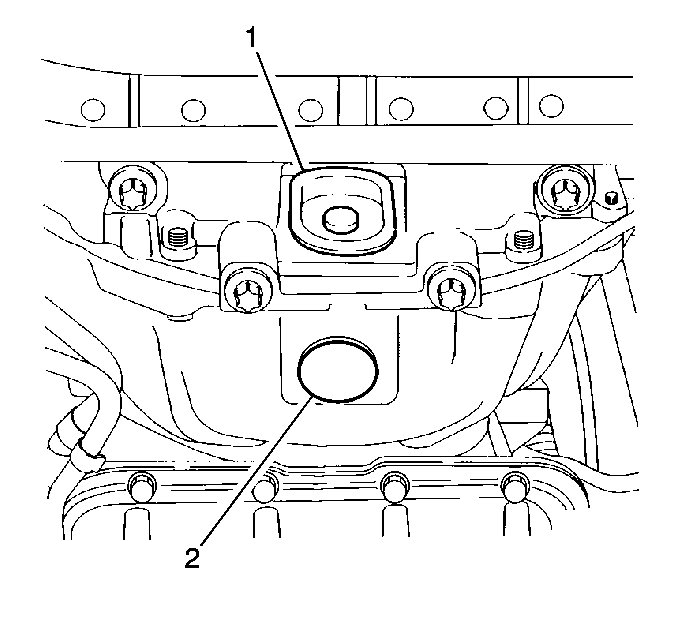
- Install the access hole
plugs on the following components:
| • | The transmission oil pan (1) |
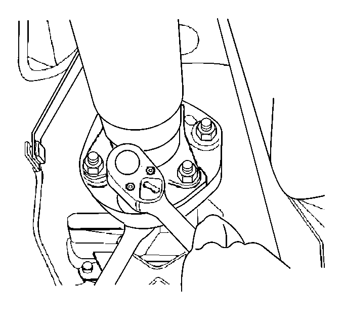
- Install the propeller shaft coupling
to the drive flange.
- Tighten the propeller shaft coupling bolts.
Tighten
Tighten the propeller shaft coupling bolts to 95 N·m (70 lb ft).
- Install the shift linkage. Refer to
Shift Control Linkage Replacement
.
- Adjust the shift linkage. Refer to
Shift Control Linkage Adjustment
.
- Fill the transmission with DEXRON® III. Refer to
Transmission Fluid Check
.
- Lower the vehicle.


