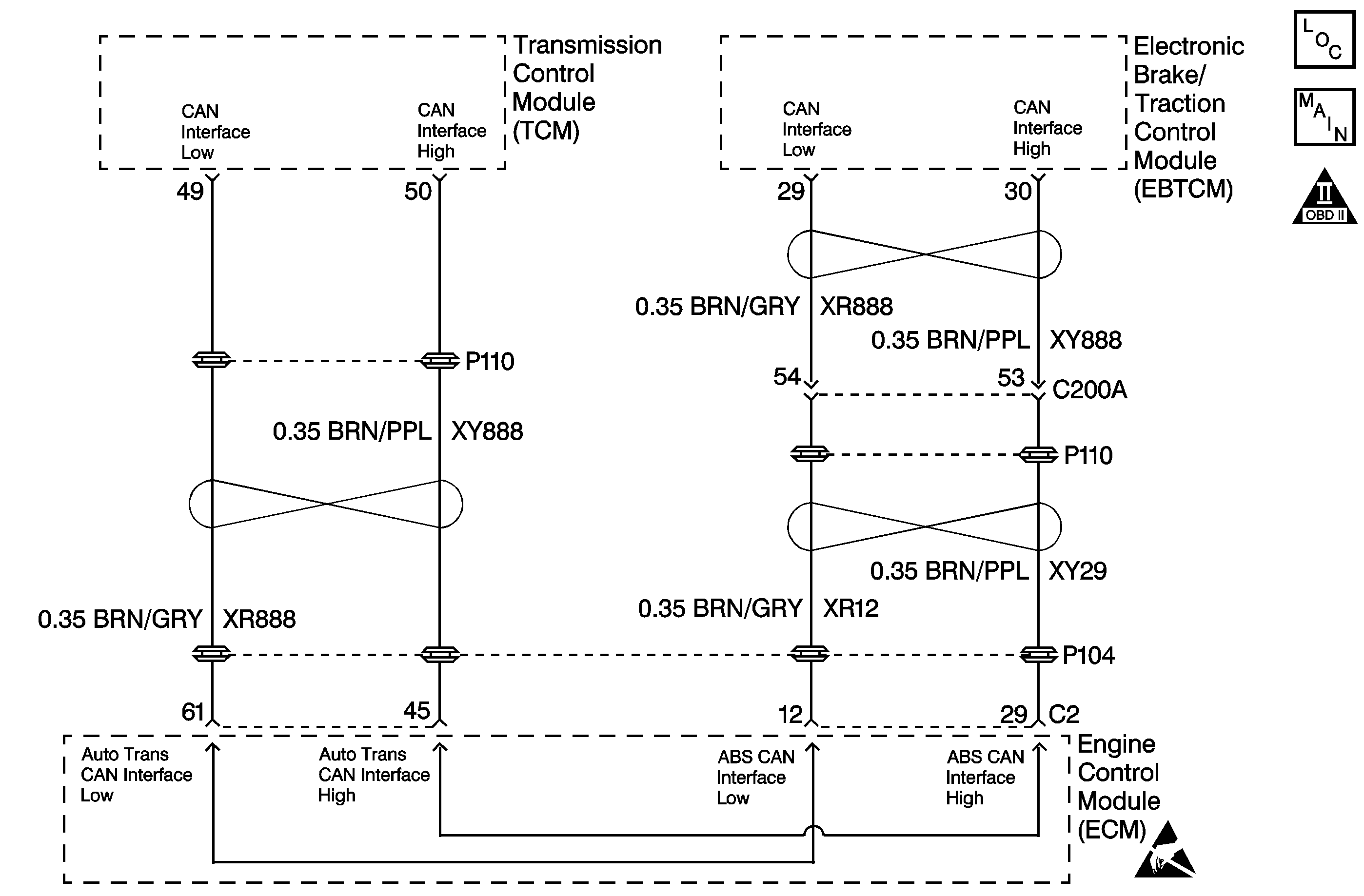
Circuit Description
Brake switch information (signal) is sent to the transmission control module (TCM) by the Engine Control Module (ECM) through a communication network called the controller area network (CAN). Circuits XR888 and XY888 are used to communicate CAN data between the ECM and TCM. When the TCM detects the loss of brake input from the ECM for a specified amount of time, then DTC P0703 will set. DTC P0703 is a type C DTC.
Condition For Running The DTC
Transmission output speed is greater than 192 RPM.
Condition For Setting The DTC
The TCM does not receive brake switch input from the ECM for 20 minutes.
Action Taken When the DTC Sets
| • | The MIL will not illuminate. |
| • | The ECM records the operating conditions in the Failure Records at the time of the DTC request from the TCM. |
| • | The TCM memory stores the DTC at the time of the first failure. |
Conditions for Clearing the MIL/DTC
| • | A History DTC clears after forty consecutive warm-up cycles, if no failures are present by this diagnostic or any other emission related diagnostic. |
| • | The scan tool clears the DTC. |
Diagnostic Aids
| • | Inspect the Brake Switch for proper adjustment. |
| • | Check for communication CAN code DTC U2105 or U2100. |
| • | Check the ECM for related DTCs. |
Test Description
The numbers below refer to the step number on the diagnostic table.
P0703 Brake Switch Circuit Malfunction
Step | Action | Value(s) | Yes | No |
|---|---|---|---|---|
1 | Did you perform the Transmission On-Board Diagnostic (OBD) System Check? | -- | ||
2 |
Important: Before clearing the DTC, use the Scan Tool in order to record the Failure Records. Using the Clear Info function erases the Failure Records from the ECM/TCM. Does the Brake Switch status display Applied when the brake pedal is depressed and Released when the pedal is released? | -- | Go to Diagnostic Aids | |
3 |
Is the fuse open? | -- | ||
Check circuit A13, A401, and FB101 for a short to ground. Did you find the condition? | -- | |||
5 | Check circuit A13, A401, and FB101 for an open. Did you find the condition? | -- | ||
6 | Replace the brake switch. Refer to Stop Lamp Switch Replacement in Hydraulic Brakes. Did you complete the replacement? | -- | -- | |
7 | Make the necessary wiring repairs. Refer to Wiring Repairs in Wiring Systems. Did you complete the repair? | -- | -- | |
8 | Perform the following procedure in order to verify the repair:
Does the Brake Switch status display Applied when the brake pedal is depressed and Released when the pedal is released? | -- | System OK |
