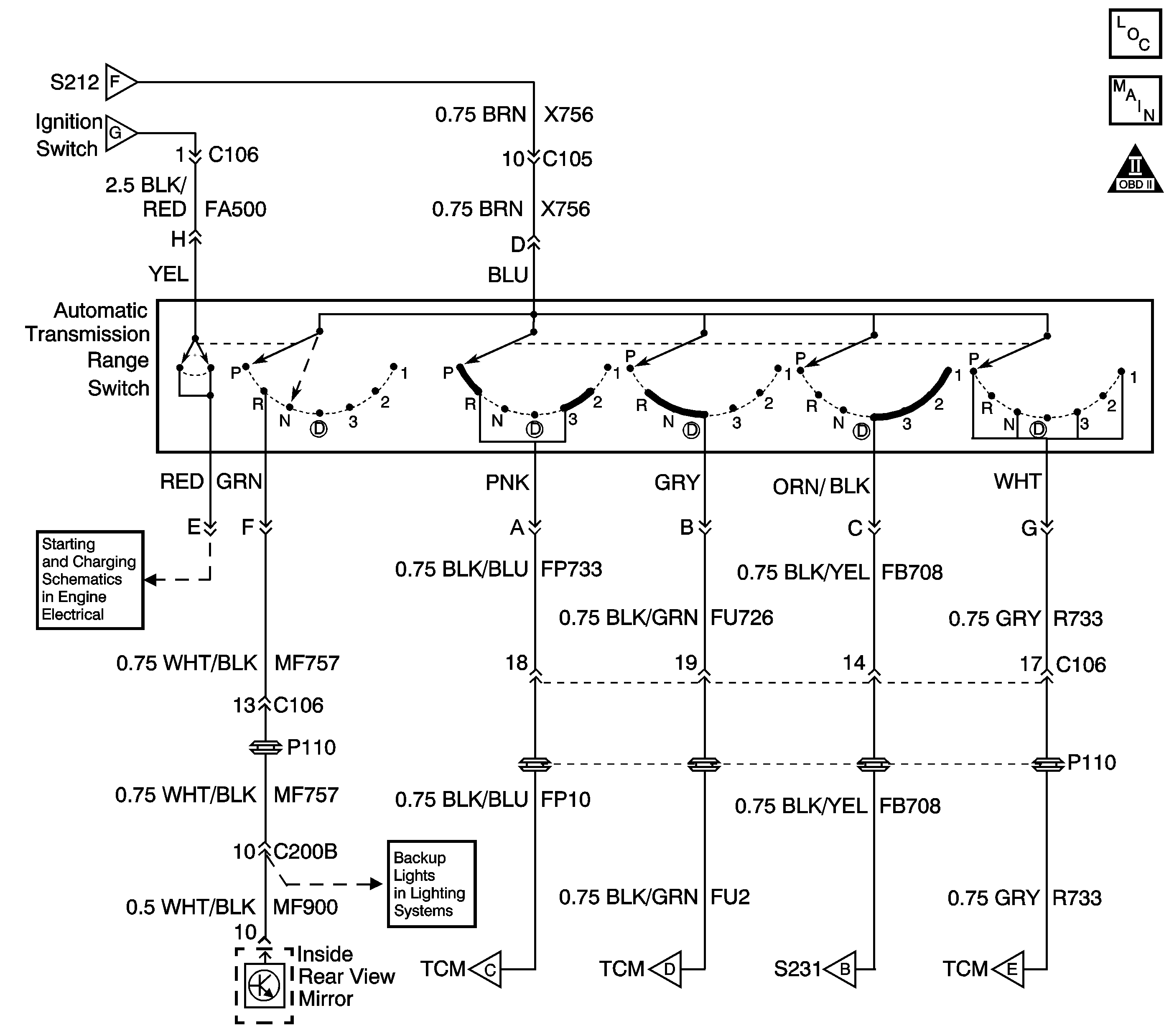
Circuit Description
The AT manual shaft shift position switch attaches externally to the left side of the 4L30-E transmission on the gear selector shaft. The AT manual shaft shift position switch informs the TCM and the console gear position indicator which gear the driver selects.
The ignition voltage is supplied to the switch on terminal D. Depending on the selector lever position, this ignition voltage connects to the various combinations of terminals A, B, C, and G of the AT manual shaft shift position switch. The TCM decodes these combinations in order to determine the gear position. When the TCM detects Park or Neutral with throttle position and engine speed for a period of time or the TCM detects Reverse with high transmission output speed, then DTC P0706 will set. DTC P0706 is a type C DTC.
The title of this DTC contains a generic part name. The specific 4L30-E part the title refers to is named the Manual Shaft Shift Position Switch.
Conditions for Running the DTC
Condition 1:
For Position N or P:
| • | The engine speed is greater than 500 RPM but less than 3008 RPM. |
| • | The throttle position is greater than 34 percent. |
| • | DTC P0120 is not set. |
Condition 2:
For Position R:
The transmission output speed is greater than 8160 RPM.
Conditions for Setting the DTC
Condition 1:
Position N or P is detected.
Condition 2:
Position R is detected.
Action Taken When the DTC Sets
| • | The MIL will not illuminate. |
| • | The ECM records the operating conditions in the Failure Records at the time of the DTC request from the TCM. |
| • | The TCM memory stores the DTC at the time of the first failure. |
Conditions for Clearing the DTC
| • | A History DTC clears after forty consecutive warm-up cycles, if no failures are present by this diagnostic or any other emission related diagnostic. |
| • | The scan tool clears the DTC. |
Diagnostic Aids
Use the J 35616 connector test adapter kit for any test that requires probing the TCM harness connector or the trans range switch harness connector. Using this kit will prevent damage to the harness connector terminals. Do not use the test adapter kit for testing on the Automatic Transmission Control Indicator Connector. This will re-size the female terminals.
Check for the following conditions:
| • | Poor connections at the TCM or at the component. Inspect the harness connectors for any backed out terminals, improper mating, broken locks, improperly formed or damaged terminals, and poor terminal to wire connection. |
| Refer to General Electrical Diagnosis in Wiring Systems for proper procedure. |
| • | Damaged harness. Inspect the wiring harness for damage. If the harness appears to be OK, observe the scan tool while moving any related connectors and any wiring harnesses. A change in the display may help to locate the fault. |
| • | If the Manual Shaft Shift Position Switch is electrically faulty, P0705 will set. If P0705 is set with P0706, diagnose and repair P0705 first. |
Test Description
The numbers below refer to the step numbers on the diagnostic table.
-
The Scan Tool display should match the selector lever position at each detent. If you have to move the lever slightly within a position to get the right indication on the Scan Tool , the Transmission Range Switch adjustment should be checked. Refer to Manual Shift Shaft Position Switch Replacement .
Step
| Action | Value(s) | Yes | No | ||||||||||
|---|---|---|---|---|---|---|---|---|---|---|---|---|---|---|
1 | Did you perform the Transmission On-Board Diagnostic (OBD) System Check? | -- | ||||||||||||
Does each selected transmission range match the Scan Tool Manual Shaft Shift Position Switch display? | Go to Diagnostic Aids | |||||||||||||
3 | Inspect the Manual Shaft Shift Position Switch for:
Did you find and correct the condition? | -- | ||||||||||||
4 | Replace the Manual Shaft Shift Position Switch. Refer to Manual Shift Shaft Position Switch Replacement . Did you complete the replacement? | -- | -- | |||||||||||
5 | Perform the following procedure in order to verify the repair:
Did DTC P0706 reset? | -- | System OK |
