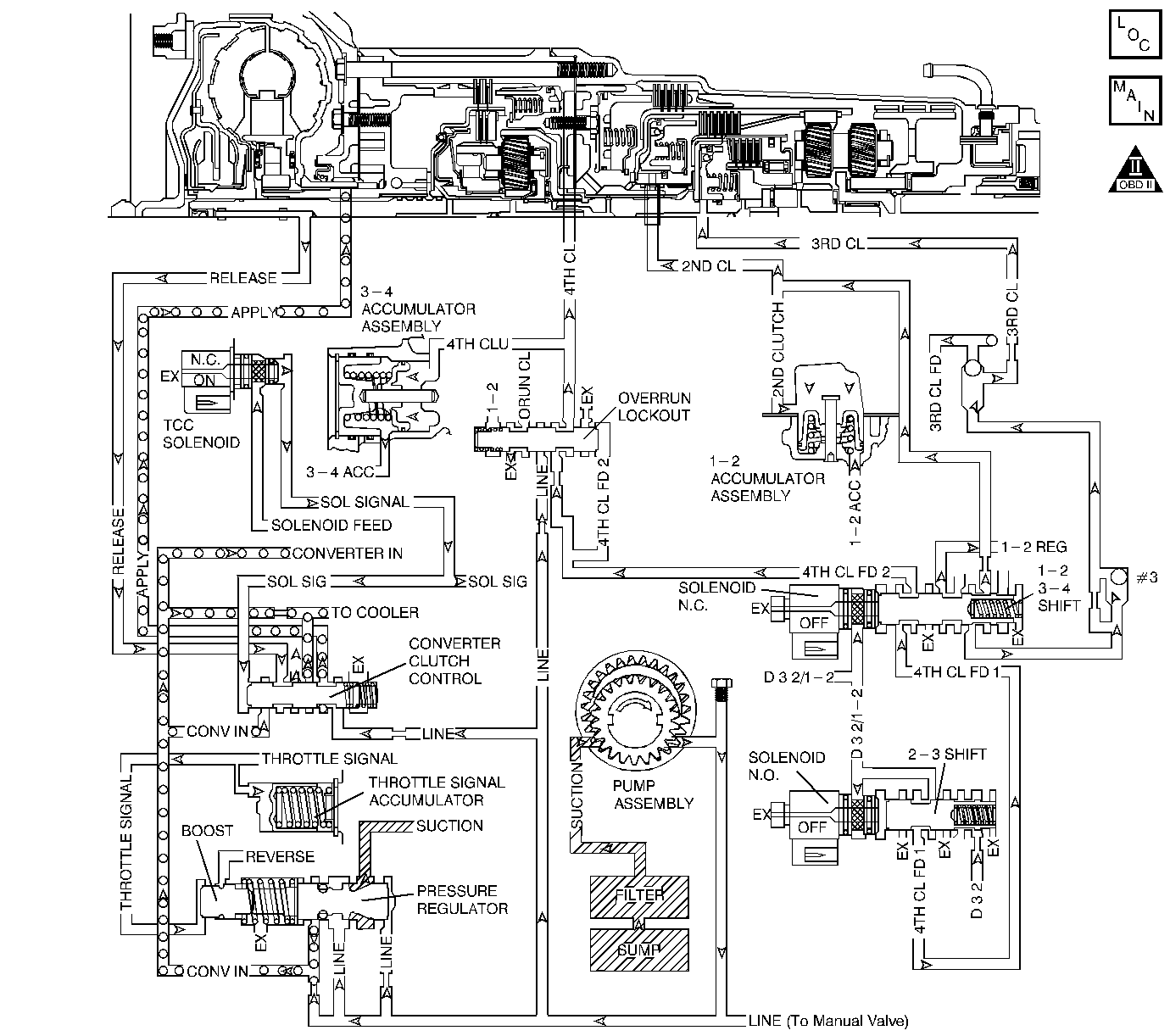
Circuit Description
The transmission control module (TCM) monitors the engine speed, the transmission output speed and current gear. The TCM calculates turbine shaft speed and torque converter clutch (TCC) slip speed by using these inputs. In D3 drive range with the TCC engaged, the engine speed should closely match the transmission output speed. In D4 drive range, with the TCC engaged, the TCC slip speed should be -20 to +64 RPM. The table above indicates solenoid states and transmission components that apply during 4th gear with the TCC commanded ON.
When the TCM detects excessive TCC slip when the TCC should be engaged, then DTC P1870 sets. DTC P1870 is a type B DTC.
Conditions for Running the DTC
| • | Transmission is not in P, R, or N. |
| • | Transmission is not in default mode. |
| • | TCC is commanded on. |
| • | No incorrect gear ratio DTC P0730. |
| • | The following code enabling and fail conditions are not met: |
| - | P0751 fail cases 1 and 2 |
| - | P0752 fail cases 1 and 2 |
| - | P0757 fail cases 1 and 2 |
Condition for Setting the DTC
TCM calculated transmission slip is greater than 288 RPM.
Action Taken When the DTC Sets
| • | The TCM flashes the sport mode lamp and sends a MIL request to the ECM on the second consecutive drive trip that the diagnostic runs and fails. The ECM then illuminates the MIL. |
| • | The ECM records the operating conditions in the Freeze Frame at the time of the MIL request from the TCM. |
| • | The transmission operates in the default mode (maximum line pressure, command 4th gear, inhibit TCC, freeze shift adapts). |
Conditions For Clearing the MIL/DTC
| • | The ECM turns off the MIL after three consecutive drive trips during which the TCM sends no MIL request. |
| • | A History DTC clears after forty consecutive warm-up cycles, if no failures are present by this diagnostic or any other emission related diagnostic. |
| • | The scan tool clears the MIL/DTC. |
| • | The TCM cancels the DTC default mode actions when the ignition switch is Off long enough in order to power down the TCM. |
Diagnostic Aids
| • | DTC P0722 could cause DTC P1870 to set falsely. |
| • | A mechanical failure of the shift solenoids or TCC solenoid valve can set DTC P1870. |
| • | Internal transmission failures can result in a DTC P1870. |
| • | Sticking or contaminated shift valves may cause intermittent slipping in D4. |
| Refer to Range Reference . |
| • | First diagnose and clear any engine DTCs or TP sensor codes that are present. Then inspect for any transmission DTCs that may have reset. |
Test Description
The number below refers to the step number on the diagnostic table.
Step | Action | Value(s) | Yes | No | ||||||||||||||||||
|---|---|---|---|---|---|---|---|---|---|---|---|---|---|---|---|---|---|---|---|---|---|---|
1 | Did you perform the Powertrain On-Board Diagnostic (OBD) System Check? | -- | Go to A Powertrain On Board Diagnostic (OBD) System Check | |||||||||||||||||||
2 | Perform the transmission fluid checking procedure. Refer to Transmission Fluid Check . Did you perform the fluid checking procedure? | -- | Go to Transmission Fluid Check | |||||||||||||||||||
Important: Before clearing the DTC, use the Scan Tool in order to record the Freeze Frame and Failure Records. Using the Clear Info function erases the Freeze Frame and Failure Records from the ECM/TCM. Is the Scan Tool TCC Slip Speed greater than the specified range? | 288 RPM | Go to Diagnostic Aids | ||||||||||||||||||||
4 | Inspect the torque converter clutch solenoid valve (TCC solenoid valve) for the following conditions:
Did you find a condition? | -- | ||||||||||||||||||||
5 |
Did you find a condition? | -- | ||||||||||||||||||||
6 | Inspect the valve body assembly for a stuck Converter Clutch Control valve. Refer to Transmission Overhaul in the 4L30-E Section of the Transmission Unit Repair. Did you find a condition? | -- | ||||||||||||||||||||
7 | Inspect the torque converter assembly for the following conditions:
Did you find a condition? | -- | ||||||||||||||||||||
8 | Inspect the oil pump assembly for the following conditions:
Refer to Transmission Overhaul in the 4L30-E Section of the Transmission Unit Repair. Did you find a condition? | -- | ||||||||||||||||||||
9 | Inspect the turbine shaft for the following conditions:
Refer to Transmission Overhaul in the 4L30-E Section of the Transmission Unit Repair. Did you find a condition? | -- | ||||||||||||||||||||
10 | Inspect the 4th clutch assembly for the following conditions:
Refer to Transmission Overhaul in the 4L30-E Section of the Transmission Unit Repair. Did you find a condition? | -- | ||||||||||||||||||||
11 | Inspect the 3rd clutch assembly for the following conditions:
Refer to Transmission Overhaul in the 4L30-E Section of the Transmission Unit Repair. Did you find a condition? | -- | ||||||||||||||||||||
12 | Inspect the 2nd clutch assembly for the following conditions:
Refer to Transmission Overhaul in the 4L30-E Section of the Transmission Unit Repair. Did you find a condition? | -- | Go to Diagnostic Aids | |||||||||||||||||||
13 | Perform the following procedure in order to verify the repair:
Is the Scan Tool TCC Slip Speed less than the specified value? | 288 RPM | System OK |
