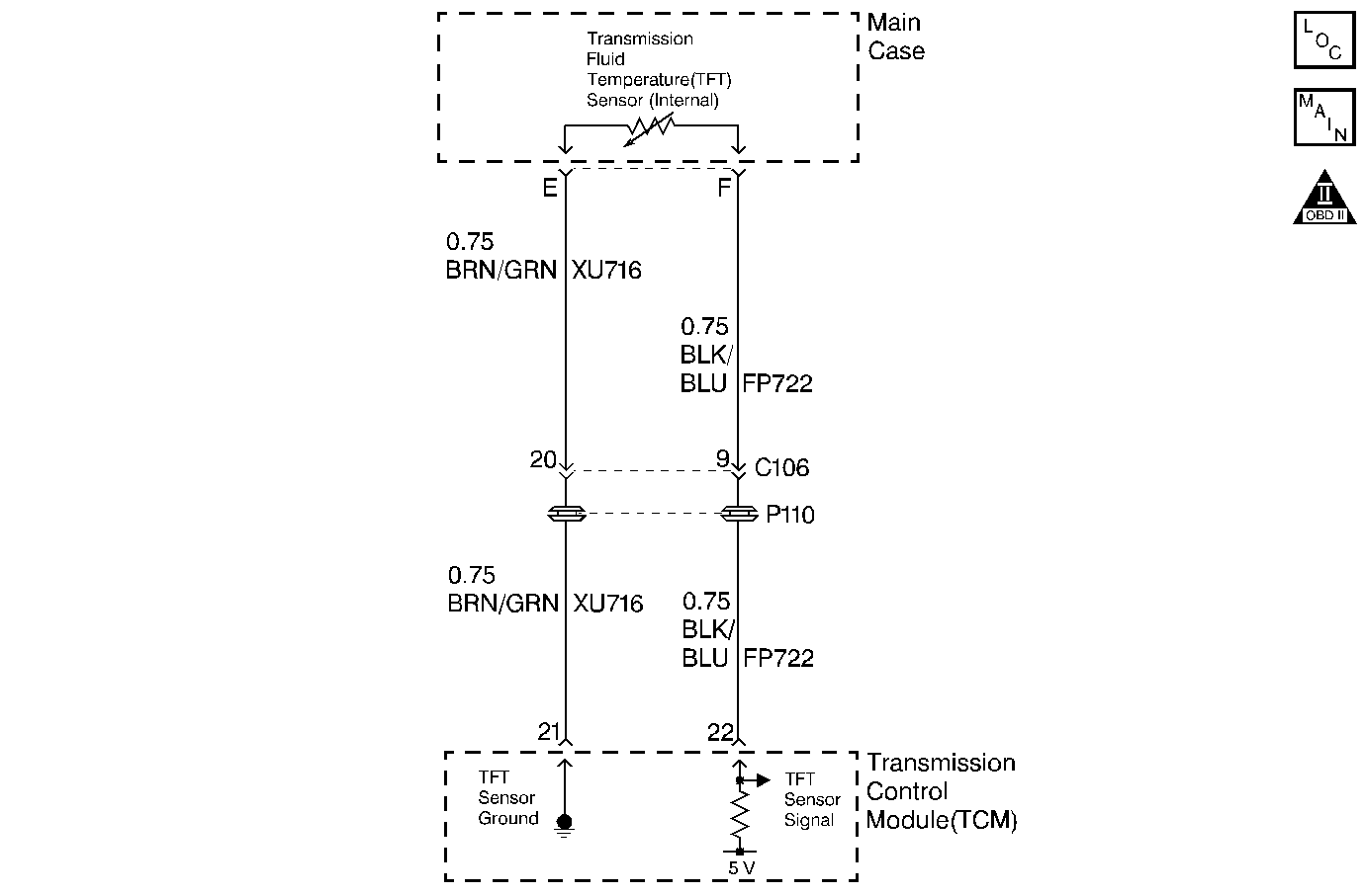
Circuit Description
The automatic transmission fluid temperature (TFT) sensor is part of the 4L30-E automatic transmission wiring harness assembly. The TFT sensor is a resistor, or thermistor, which changes value based on temperature. The sensor has a negative-temperature coefficient. This means that as the temperature increases, the resistance decreases, and as the temperature decreases, the resistance increases. The transmission control module (TCM) supplies a 5-volt reference signal to the sensor on circuit FP722 and measures the voltage drop in the circuit. When the transmission fluid is cold, the sensor resistance is high and the TCM detects high signal voltage. As the fluid temperature warms to a normal operating temperature, the resistance becomes less and the signal voltage decreases.
If the TCM detects a short to power in the TFT sensor or signal circuit, then DTC P0713 sets. DTC P0713 is a type C DTC.
Condition for Running the DTC
The ignition Switch is in the RUN position.
Condition for Setting the DTC
TFT is above 4.35 Volts for 20 seconds.
Action Taken When the DTC Sets
| • | The TCM flashes the sport mode lamp. |
| • | The ECM records the operating conditions in the Failure Records at the time of the request from the TCM. |
| • | The TCM memory stores the DTC at the time of the first failure. |
| • | The transmission temperature defaults to 130°C (266°F). |
| • | The TCM will freeze shift adapts. |
Conditions for Clearing the STL/DTC
| • | The TCM stops flashing the sport mode lamp as soon as the fault is no longer present. |
| • | A History DTC clears after forty consecutive warm-up cycles, if no failures are present by this diagnostic or any other emission related diagnostic. |
| • | The scan tool clears the DTC. |
| • | The TCM cancels the DTC default actions when the fault no longer exists. |
Diagnostic Aids
Use the J 35616 connector test adapter kit for any test that requires probing the TCM harness connector or a component harness connector. Using this kit will prevent damage to the harness connector terminals.
Check for the following conditions:
| • | Poor connections at the TCM or at the component. Inspect the harness connectors for any backed out terminals, improper mating, broken locks, improperly formed or damaged terminals, and poor terminal to wire connection. |
| Refer to General Electrical Diagnosis in Wiring Systems for proper procedure. |
| • | Damaged harness. Inspect the wiring harness for damage. If the harness appears to be OK, observe the scan tool while moving any related connectors and any wiring harnesses. A change in the display may help to locate the fault. |
Test Description
The numbers below refer to the step numbers on the Diagnostic Table.
-
This step tests the TCMs ability to detect low voltage. If the TCM recognizes low voltage, this eliminates the TCM and the wiring up to the transmission connector from having the fault. The fault must be internal to the transmission.
-
This step checks for higher than normal circuit voltage, (greater than 7.0 volts) which will cause the TFT to fail. If the voltage level caused the TFT to fail, then the transmission harness must be replaced.
-
Since the TFT is an integral part of the transmission wiring, the entire harness must be replaced.
Step | Action | Value(s) | Yes | No |
|---|---|---|---|---|
1 | Did you perform the Transmission On-Board Diagnostic (OBD) System Check? | -- | ||
2 |
Important: Before clearing the DTC, use the Scan Tool in order to record the Failure Records. Using the Clear Info function erases the Failure Records from the ECM/TCM. Observe the Scan Tool TFT Sensor voltage. Does the Scan Tool display a TFT Sensor voltage greater than the specified value? | 4.35 volts | Go to Diagnostic Aids | |
Does the Scan Tool display a TFT Sensor voltage less than the specified value? | 0.09 volts | |||
4 | Check circuit FP 722 from the transmission 7-way connector to the TCM for an open. Did you find the condition? | -- | ||
5 | Check circuit FP 722 from the transmission 7-way connector to the TCM for a short to power. Did you find the condition? | -- | ||
6 | Check the transmission internal wiring circuit FP 722 (green wire) for an open. Did you find the condition? | -- | ||
Check the transmission internal wiring circuit FP 722 (green wire) or the TFT for being shorted to Circuit PF 954 (brown wire). Did you find the condition? | -- | -- | ||
8 | Make the necessary wiring repairs. Refer to Wiring Repairs in Wiring Systems. Did you complete the repair? | -- | -- | |
Replace the main case harness assembly. Refer to Control Valve Body . Did you complete the replacement? | -- | -- | ||
10 | Replace the TCM. Refer to Transmission Control Module Replacement . Did you complete the replacement? | -- | -- | |
11 | Perform the following procedure in order to verify the repair:
Does the Scan Tool display a TFT sensor voltage less than the specified value? | 4.35 volts | System OK |
