For 1990-2009 cars only
Removal Procedure
Caution: This vehicle is equipped with a Supplemental Inflatable Restraint (SIR) System. Failure to follow the correct procedure could cause the following conditions:
• Air bag deployment • Personal injury
In order to avoid the above conditions, observe the following guidelines:
• Unnecessary SIR system repairs • Refer to SIR Component Views in order to determine if you are performing service on or near the SIR components or the SIR wiring. • If you are performing service on or near the SIR components or the SIR wiring, disable the SIR system. Refer to Disabling the SIR System.
- Disable the SIR system. Refer to Disabling the SIR System in Restraints.
- Remove the steering wheel inflator module. Refer to Inflatable Restraint Steering Wheel Module Replacement in Restraints.
- Remove the steering wheel. Refer to Steering Wheel Replacement
- Remove the tilt lever. Refer to Tilt Lever Replacement - On Vehicle
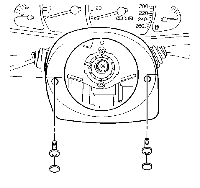
- Remove the screw caps from the upper steering column cover.
- Remove the screws from the upper steering column cover.
- Remove the upper steering column cover.
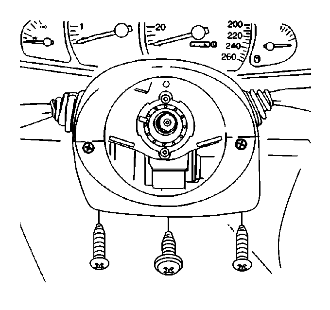
- Remove the screws from the lower steering column cover.
- Remove the lower steering column cover.
- Remove the inflatable restraint steering wheel module coil. Refer to Inflatable Restraint Steering Wheel Module Coil Replacement
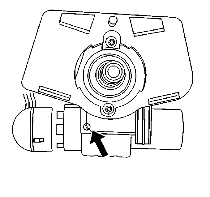
- Remove the ignition switch set screw.
- Turn the ignition switch to the ON position.
- Remove the lifting magnet from the ignition switch.
- Insert a small flatbladed tool into the ignition switch electrical connector hole in order to depress the locking tab.
- Disconnect the electrical connector from the ignition switch.
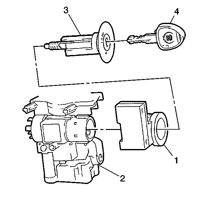
- Remove the ignition lock cylinder(3). Refer to Ignition Lock Cylinder Replacement - On Vehicle
- Disconnect the electrical connector from the theft deterent module (1).
- Remove the theft deterent module (1) from the ignition lock cylinder housing(2).
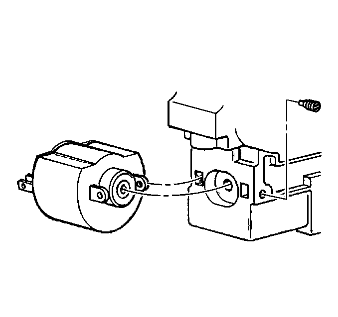
- Pull ignition switch toward the rear of the vehicle and slide to the left to remove the ignition switch from the ignition lock cylinder housing.
Installation Procedure
- Install the ignition switch to the lock cylinder housing.
- Install the theft deterent module (1) to the ignition lock cylinder housing(2).
- Connect the electrical connector to the theft deterent module (1).
- Install the ignition lock cylinder(3). Refer to Ignition Lock Cylinder Replacement - On Vehicle
- Connect the electrical connector to the ignition switch.
- Install the ignition switch set screw until fully seated and not stripped.
- Install the lifting magnet to the ignition switch.
- Install the inflatable restraint steering wheel module coil. Refer to Inflatable Restraint Steering Wheel Module Coil Replacement in Restraints.
- Install the lower steering column cover.
- Install the screws to the lower steering column cover.
- Install the upper steering column cover.
- Install the screws to the upper steering column cover.
- Install the screw caps to the upper steering column cover.
- Install the tilt lever. Refer to Tilt Lever Replacement - On Vehicle
- Install the steering wheel. Refer to Steering Wheel Replacement
- Install the steering wheel inflator module. Refer to Inflatable Restraint Steering Wheel Module Replacement in Restraints.
- Enable the SIR system. Refer to Enabling the SIR System in Restraints.


