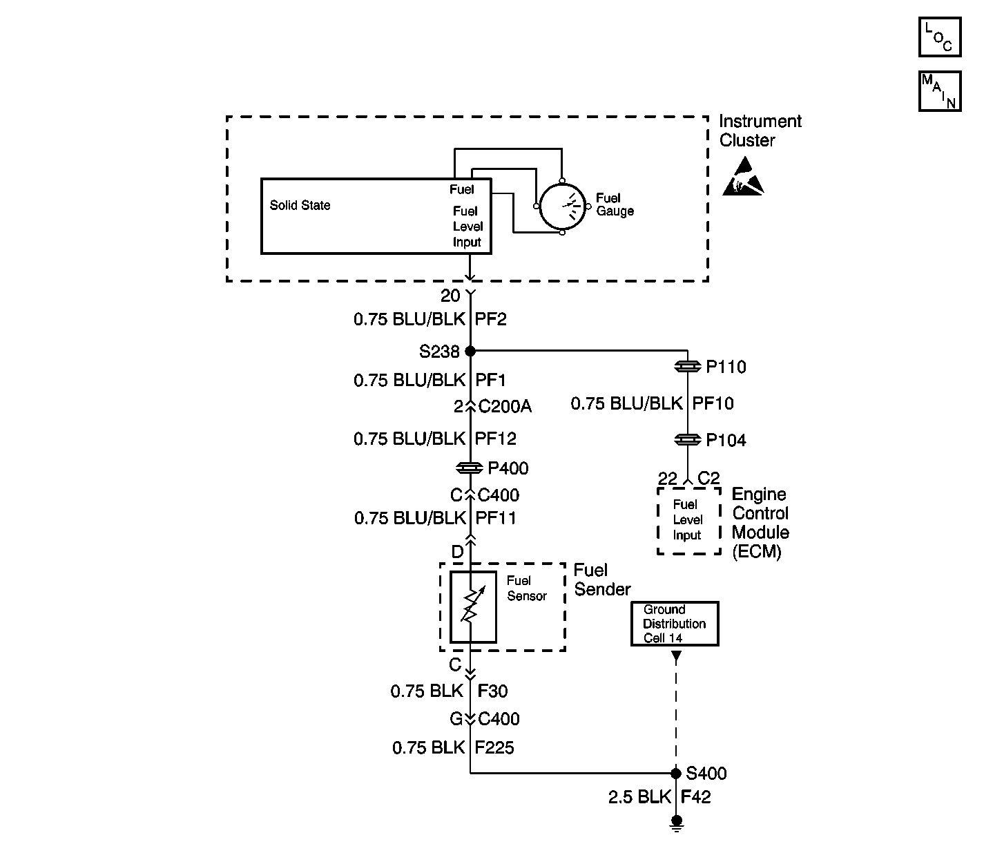
Circuit Description
A microprocessor in the instrument cluster sends voltage to the fuel tank sensor contained inside the fuel tank. A float arm, which is attached to the sensor, changes position with the fuel level in the tank. The fuel sensor is a variable resistor. As the fuel level changes, the resistance of the fuel sensor changes. The instrument cluster monitors changes in the voltage caused by the changes in the resistance of the sensor in order to determine fuel level.
Conditions for Setting the DTC
The fuel gauge circuit is tested every 100 ms. DTC 167 will set in the following ways:
| • | When the circuit is shorted to ground. |
| • | The resistance of the fuel sensor is out of range (less than 30 ohms) for more than 8 seconds. |
Action Taken When the DTC Sets
| • | Stores a DTC 167 in memory. |
| • | The fuel gauge pointer will return to the zero position. |
Conditions for Clearing the DTC
| • | The resistance must be greater than 30 ohms for 4 seconds to clear the fault in the next monitoring cycle. |
| • | Conditions for the fault are no longer present. |
| • | Using a scan tool. |
Diagnostic Aids
| • | If the DTC is a history or an intermittent DTC, perform the tests shown while moving related wiring harnesses and connectors. This can often cause the malfunction to appear. Refer to Intermittents and Poor Connections Diagnosis in Wiring Systems. |
| • | Visually inspect the harness and the harness connectors for the following conditions: |
| - | Damage |
| - | Corrosion |
| - | Water intrusion |
| - | Adequate terminal tension |
| - | Mis-routed harness |
| - | Rubbed through wire insulation |
| - | Broken wire inside the insulation |
| • | Before replacing the instrument cluster, test all power and ground circuits to the cluster. Refer to Measuring Voltage Drop in Wiring Systems. |
Test Description
The numbers below refer to the step numbers on the diagnostic table.
-
This test determines if the fuel tank sensor is shorted.
-
This test determines if system voltage is present. No voltage indicates that a short to ground exists in the circuit.
-
After a circuit repair is made, test the system again in order to see if the DTC resets. If the DTC resets, the instrument cluster most likely has an internal failure.
-
This step removes the ECM from the circuit. If the ECM has an internal short, voltage supplied by the instrument cluster would be pulled to ground.
Step | Action | Values | Yes | No |
|---|---|---|---|---|
1 | Did you perform the Instrument Cluster Diagnostic System Check? | -- | Go to Step 2 | |
Is the resistance reading less than the indicated value? | 30 ohms | Go to Step 3 | Go to Step 4 | |
3 | Replace the fuel tank sender. Is the replacement complete? | -- | Go to Step 7 | -- |
Is the voltage reading within the specified range? | B+ | Go to Step 5 | Go to Step 6 | |
5 | Move related harnesses and harness connectors while monitoring the DMM. Did you find and repair a circuit problem? | -- | Go to Step 7 | Go to Diagnostic Aids |
6 |
Is the voltage reading within the specified range? | B+ | Go to Step 8 | Go to Step 9 |
Is a current DTC 167 set? | -- | Go to Step 10 | System OK | |
8 | Repair the short to ground between C200A terminal 2 and C400 terminal C (CKT PF12). Is the repair complete? | -- | Go to Step 7 | -- |
Is the voltage reading within the specified range? | B+ | Go to Step 12 | Go to Step 11 | |
10 | Replace the instrument cluster. Refer to Instrument Cluster Replacement . Is the replacement complete? | -- | -- | |
11 |
Did you locate a short to ground in the circuits? | -- | Go to Step 13 | -- |
12 | Replace the ECM. Refer to Engine Control Module Replacement/Programming in Engine Controls. Is the replacement complete? | -- | Go to Step 7 | -- |
13 | Repair the short to ground in CKT PF1 (BLU/BLK) or CKT PF10 (BLU/BLK). Is the repair complete? | -- | Go to Step 7 | -- |
