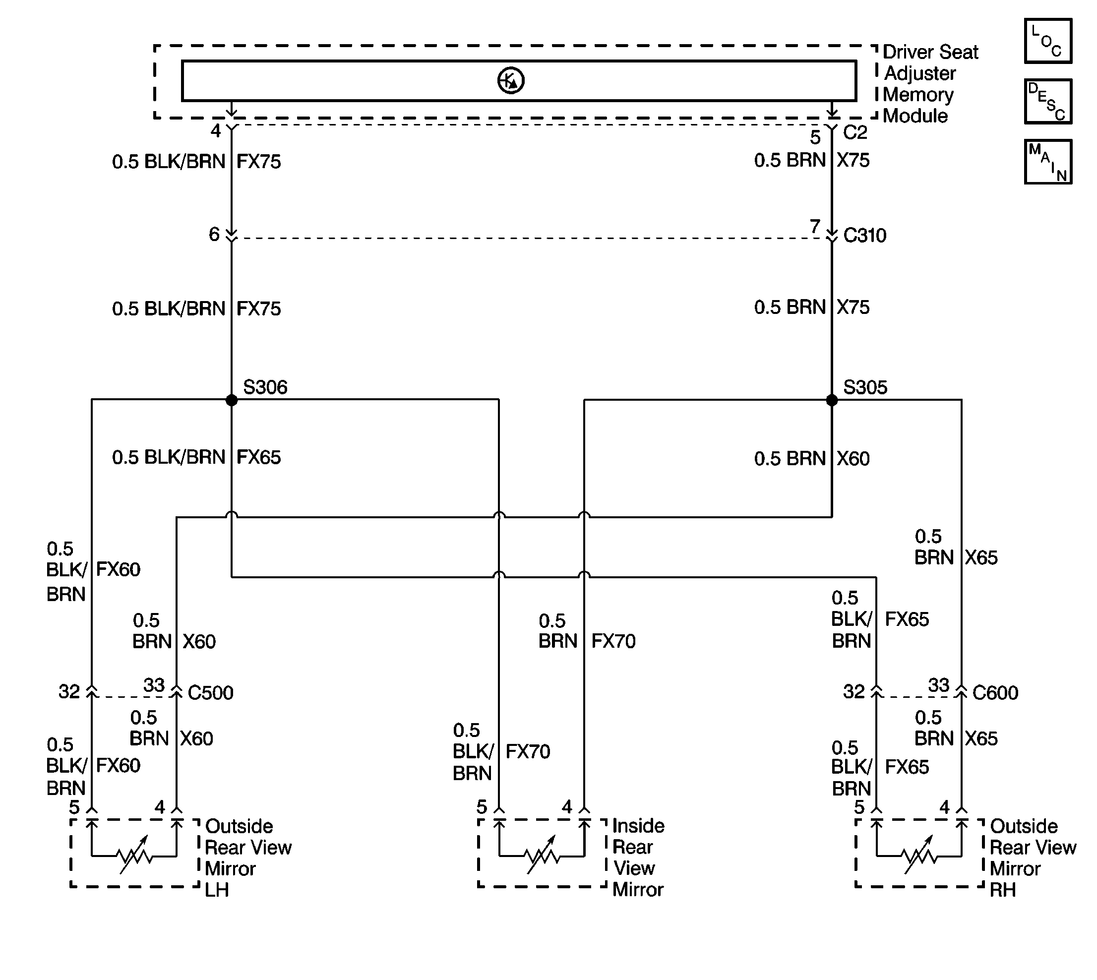
LH, RH and Inside Rear View Mirrors

Circuit Description
The driver seat adjuster memory module monitors the reference voltage of all three rear view mirror potentiometers using terminals 4 and 5 of the driver seat adjuster memory module connector C2. The normal voltage reading should be +5V. If the voltage reading is not in the normal range, the driver seat adjuster memory module sets DTCs 18, 19 and 20.
Conditions for Setting the DTCs
DTC 18, 19, and 20 will set if:
| • | there is a short to voltage in any of the circuits related to terminals 4 and 5 of the driver seat adjuster memory module connector C2. |
| • | there is a short to ground or an open in any of the circuits related to terminals 4 and 5 of the driver seat adjuster memory module connector C2. |
| • | there is a failure within the LH or RH outside rear view or the inside rear view mirror potentiometers. |
| • | there is an internal failure within the driver seat adjuster memory module. |
Action Taken When the DTCs Set
| • | The driver seat adjuster memory module will store DTCs 18, 19 and 20. |
| • | The automatic adjustment of all three rear view mirrors is blocked. |
| • | The adjustment speed of all three rear view mirror motors is not monitored (i.e. blocking end of the affected motor is not recognized). |
| • | The end stops of all three rear view mirror motors is not monitored (i.e. the affected motor is not switched off when it reaches its programmed end stop). |
| • | The position of all motors is not stored in the driver seat adjuster memory module. |
Conditions for Clearing the DTCs
| • | DTCs 18, 19 and 20 will clear when the conditions for the fault are no longer present. |
| • | DTCs 18, 19 and 20 can be cleared by using the scan tool. |
Diagnostic Aids
| • | Check for an open, high resistance, short to ground or short to voltage in circuits FX75, FX60, FX65 and/or FX70. |
| • | Check for an open, high resistance, short to ground or short to voltage in circuits X75, X60, X65 and/or X70. |
| • | Check for loose connections and damaged connectors. |
Test Description
The number(s) below refer to the step number(s) on the diagnostic table.
-
This step checks the voltage on circuits X75, X70, X65 and X60.
-
This step checks the voltage on circuits FX75, FX70, FX65 and FX60
-
This step checks the rear view mirrors motor potentiometers for an open or faulty resistance reading
Step | Action | Value(s) | Yes | No | ||||||||||||
|---|---|---|---|---|---|---|---|---|---|---|---|---|---|---|---|---|
1 | Was the Power Mirrors System Check performed? | -- | Go to Outside Mirrors System Check . | |||||||||||||
Are all the measured voltages within the specified value? | +5V | |||||||||||||||
3 |
Is the repair or replacement complete? | -- | -- | |||||||||||||
Use the DMM to measure the resistance between the following connectors and a known good ground.
Are all the measured resistances within the specified value? | Less than 5ohms | |||||||||||||||
5 |
Is the repair or replacement complete? | -- | -- | |||||||||||||
Use the DMM to measure the resistance between the following terminals of the rearview mirror motor potentiometers.
Are all the measured resistances within the specified values? | 1.25K ohms for the inside rear view mirror 1.85K ohms for the outside rearview mirrors | |||||||||||||||
7 | Replace the rear view mirror motor potentiometer that does not meet the specified value. Refer to one of the following procedures.
Is the repair complete? | -- | -- | |||||||||||||
8 |
Do all three of the rear view mirrors operate properly? | -- | System OK |
