Removal Procedure
Notice: The front wheels of the vehicle must be maintained in the straight ahead position and the steering column must be in the LOCK position before disconnecting the steering column or intermediate shaft. Failure to follow these procedures will cause improper alignment of some components during installation and result in damage to the SIR coil assembly.
Notice: Once the steering column is removed from the vehicle, the column is extremely susceptible to damage. Dropping the column assembly on the end could collapse the steering shaft or loosen the plastic injections, which maintain column rigidity. Leaning on the column assembly could cause the jacket to bend or deform. Any of the above damage could impair the columns collapsible design. Do NOT hammer on the end of the shaft, because hammering could loosen the plastic injections, which maintain column rigidity. If you need to remove the steering wheel, refer to the Steering Wheel Replacement procedure in this section.
- Disable the SIR system. Refer to Disabling the SIR System in SIR.
- Remove the steering wheel inflator module. Refer to Inflatable Restraint Steering Wheel Module Replacement in Restraints.
- Remove the steering wheel. Refer to Steering Wheel Replacement .
- Remove the SIR coil. Refer to Inflatable Restraint Steering Wheel Module Coil Replacement in Restraints.
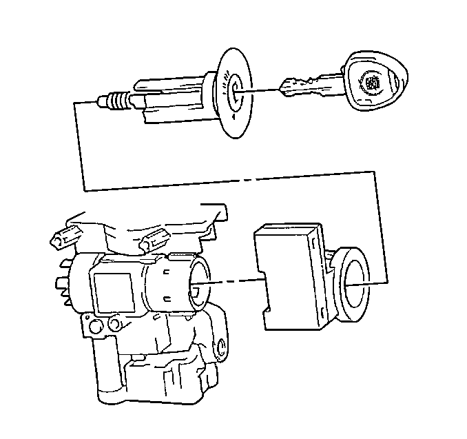
- Remove the ignition lock cylinder. Refer to Ignition Lock Cylinder Replacement - On Vehicle .
- Disconnect the theft deterrent immobilizer connector.
- Remove the immobilizer.
- Remove the ignition switch. Refer to Ignition Switch Replacement - On Vehicle .
- Remove the windshield washer switch. Refer to Windshield Wiper and Washer Switch Replacement - On Vehicle .
- Remove the turn signal switch. Refer to Turn Signal Switch Replacement - On Vehicle .
- Remove the I/P driver knee bolster energy absorber.
- Remove the sound insulator.
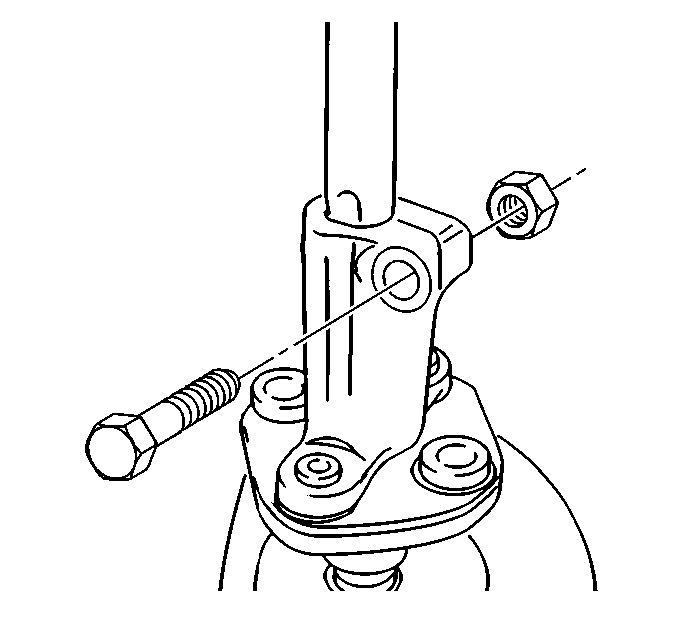
- Remove the coupler bolt from the coupler/steering column shaft connection.
- Separate the coupler in order to allow for shaft removal.
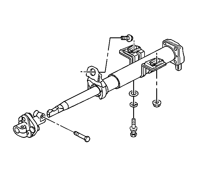
- Remove the forward support strap nut.
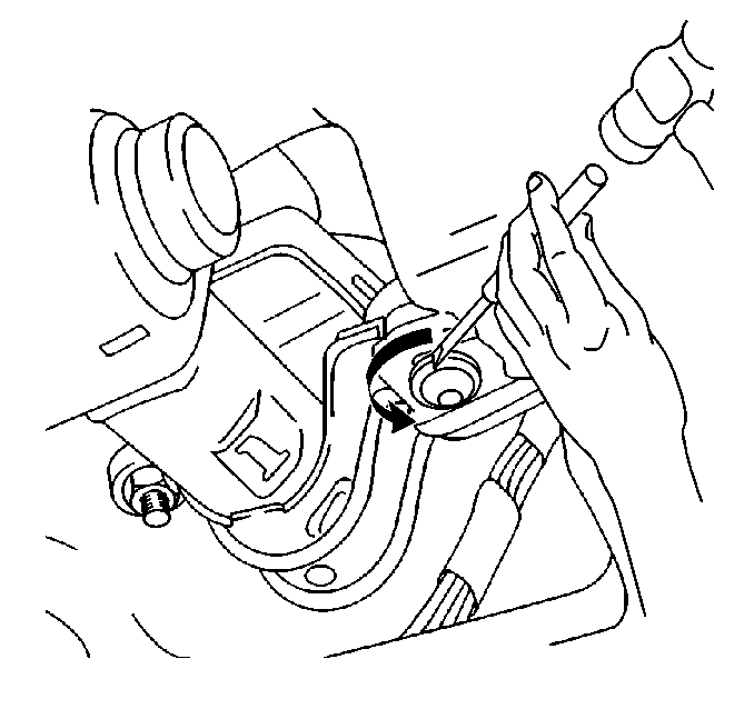
- Using a chisel, rotate the forward support strap shear-bolt in order to remove.
- Remove the rear support bracket bolt.
- Pull the steering column straight back through the cowl assembly.


Important: Use caution in the next step in order to prevent damage to the adjacent wiring.
Installation Procedure
Notice: If a service replacement steering column is being installed, do not remove the anti-rotation pin until after the column has been connected to the steering gear. Removing the antirotation pin before the column is connected to the steering gear may damage the SIR coil.
- Install the steering column while carefully aligning into the lower steering coupler.
- Handstart the following components:
- Tighten the following components:
- Install the coupler/steering column shaft connection bolt.
- Install the sound insulator.
- Install the I/P driver knee bolster energy absorber.
- Install the turn signal switch. Refer to Turn Signal Switch Replacement - On Vehicle .
- Imstall the windshield washer switch. Refer to Windshield Wiper and Washer Switch Replacement - On Vehicle .
- Install the ignition switch. Refer to Ignition Switch Replacement - On Vehicle .
- Install the immobilizer.
- Connect the immobilizer connector.
- Install the ignition lock cylinder. Refer to Ignition Lock Cylinder Replacement - On Vehicle .
- Install the SIR coil. Refer to Inflatable Restraint Steering Wheel Module Coil Replacement in Restraints.
- Install the steering wheel. Refer to Steering Wheel Replacement .
- Install the steering wheel inflator module. Refer to Inflatable Restraint Steering Wheel Module Replacement in Restraints.
- Enable the SIR system. Refer to Enabling the SIR System in SIR.

| • | The rear support bracket bolt |
| • | The forward support strap nut |
| • | A new forward support shear-bolt |
Notice: Use the correct fastener in the correct location. Replacement fasteners must be the correct part number for that application. Fasteners requiring replacement or fasteners requiring the use of thread locking compound or sealant are identified in the service procedure. Do not use paints, lubricants, or corrosion inhibitors on fasteners or fastener joint surfaces unless specified. These coatings affect fastener torque and joint clamping force and may damage the fastener. Use the correct tightening sequence and specifications when installing fasteners in order to avoid damage to parts and systems.
Tighten
| • | Tighten the rear support bracket bolt to 22 N·m (16 lb ft). |
| • | Tighten the forward support strap nut to 22 N·m (16 lb ft). |
| • | Tighten the new forward support shear-bolt to 21 N·m (15 lb ft). |

Tighten
Tighten the bolt to 22 N·m (16 lb ft).

