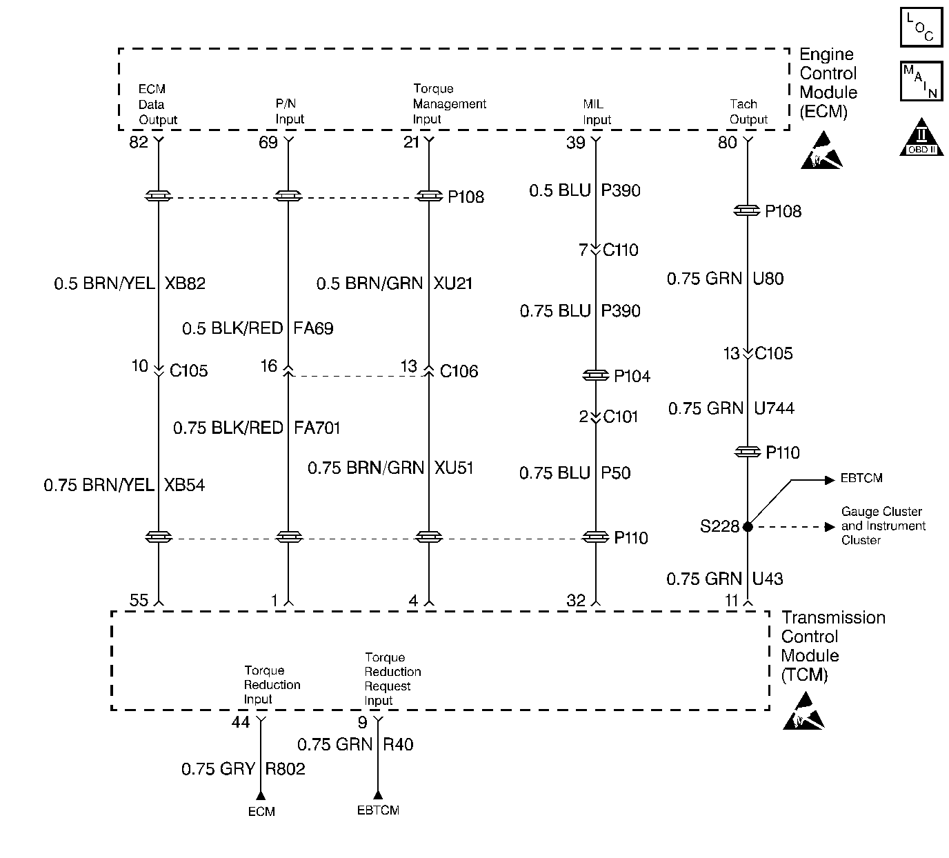
Circuit Description
This DTC indicates that a transmission related OBD II failure has occurred. The Transmission Control Module (TCM) controls a dedicated Service Transmission Lamp (STL) which illuminates when a fail reports by certain non-emissions related TCM diagnostics. The TCM has no direct control of the engine MIL, but if a transmission fault occurs that is emissions related, the engine MIL must illuminate. A MIL Request circuit between the ECM and the TCM provides a means for illuminating the MIL, even though the fault was detected by the TCM. This circuit is pulled up to B+ within the ECM. In order to illuminate the MIL, the TCM momentarily pulses. The ECM detects this and DTC P1700 is set, which illuminates the MIL. DTC P1701 indicates that the ECM has a detected problem with the MIL Request circuit.
Conditions for Running the DTC
Engine cranking
Conditions for Setting the DTC
| • | A short to ground, an open circuit, or a short to battery voltage detected on the MIL Request circuit |
| • | The condition has been present for at least 2.5 seconds. |
Action Taken When the DTC Sets
The ECM illuminates the malfunction indicator lamp (MIL) and records the operating conditions in the Freeze Frame on the second consecutive drive trip that the diagnostic runs and fails.
Conditions for Clearing the MIL/DTC
| • | The ECM turns OFF the MIL after three consecutive drive trips that the diagnostic runs and passes. |
| • | A History DTC clears after forty consecutive warm-up cycles in which no failures are reported by this diagnostic or any other emission related diagnostic. |
| • | The ECM battery voltage is interrupted. |
| • | The scan tool clears the MIL/DTC. |
Diagnostic Aids
For any test that requires probing the TCM harness connector or a component harness connector, use the Connector Test Adapter Kit J 35616 . Using this kit will prevent damage to the harness connector terminals.
Check for the following conditions:
| • | Poor connections at the ECM, TCM or at the component. Inspect the harness connectors for any backed out terminals, improper mating, broken locks, improperly formed or damaged terminals, and poor terminal to wire connection. Refer to Engine Control Module Diagnosis for the proper procedure. |
| • | Damaged harness. Inspect the wiring harness for any damage. If the harness appears to be OK, observe the scan tool while moving the related connectors and the wiring harnesses. A change in the display may help in order to locate the fault. |
Test Description
The number(s) below refer to the step number(s) on the Diagnostic Table.
Step | Action | Value(s) | Yes | No |
|---|---|---|---|---|
1 | Did you perform the Powertrain On-Board Diagnostic (OBD) System check? | -- | ||
2 |
Does the DVM indicate the specified voltage? | B+ | ||
3 | Probe the MIL Request circuit in the TCM harness connector with the test light J 34142-B connected to ground. Does the test light illuminate? | -- | ||
4 |
Is continuity indicated? | -- | ||
5 | Check the harness for continuity between the MIL request circuit and battery ground with the DVM J 39200 . Is continuity indicated? | -- | ||
Does the test light illuminate? | -- | Fault not present. Refer to Diagnostic Aids | ||
7 | Repair the circuit shorted to B+. Is the action complete? | -- | -- | |
8 | Repair the open/high resistance circuit. Is the action complete? | -- | -- | |
9 | Repair the circuit shorted to ground. Is the action complete? | -- | -- | |
10 | Replace the TCM. Is the action complete? | -- | -- | |
11 | Check for a poor connection or poor terminal tension at the ECM harness connector. Refer to Electrical Diagnosis in Engine Electrical, and Trouble Shooting Procedures for the proper procedures. Also, refer to Checking Terminal Contact in Engine Control Module Diagnosis . Was a problem found and corrected? | -- | ||
12 |
Important: This vehicle is equipped with a Theft Deterrent System which interfaces with the Engine Control Module (ECM). Program the new ECM with the frequency code of the theft deterrent module that is currently on the vehicle. Replace the ECM. Refer to Engine Control Module Replacement/Programming . Is the action complete? | -- | -- | |
13 |
Is this DTC set? | -- | ||
14 | Were there any additional DTCs noted during the Powertrain OBD System Check that have not been diagnosed? | -- | Go to the applicable DTC table | The System is OK |
