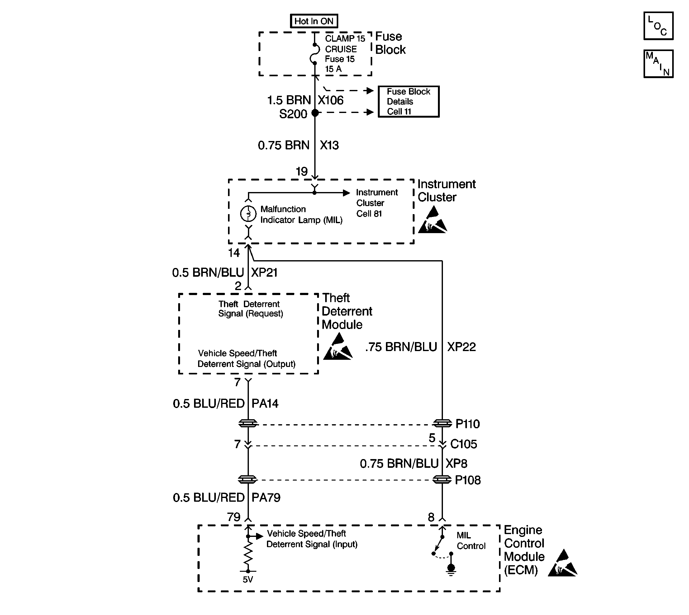
Theft Deterrent Diagnostic Circuit

Circuit Description
When the ignition switch is turned ON, the Engine Control Module (ECM) sends a signal over the lamp circuit to terminal 2 of the Theft Deterrent Module (Immobilizer) requesting the frequency code (imo signal).
After the Theft Deterrent Module receives and recognizes the signal, the Theft Deterrent Module internally blocks the speed signal output at terminal 7. The Theft Deterrent Module allows the imo signal to be transmitted out at terminal 7. The ECM receives the imo signal at terminal 79.
Conditions for Setting the DTC
- The request signal from the ECM was not received after the ignition was switched on.
- A short to ground in the imo signal request circuit between the Gauge Cluster and Theft Deterrent Module.
- An open in the imo signal request circuit between the Gauge Cluster and Theft Deterrent Module. The above conditions must be fulfilled for at least 0.51 seconds.
Action Taken When the DTC Sets
The engine will start then stall.
Conditions for Clearing the DTC
| • | Conditions for the fault are no longer present. |
| • | The ignition switch been cycled 20 times. |
| • | Using a scan tool. |
Diagnostic Aids
| • | Using a DMM, check the ground circuit at terminal 4. Typical voltage drop readings are 100mV or less. When measuring the resistance it should measure at close to 0 (zero) ohms. |
| • | Use Terminal Repair Kit J 38125-A or J 35616-A to gauge all terminal contacts. Check for damaged connectors and poor wire to terminal connections. Refer to 8A-4-5 for procedure. |
| • | If the DTC is an intermittent DTC, try performing the tests shown while "wiggling" wiring and connectors, this can often cause the malfunction to appear. |
Test Description
The number(s) below refer to the step number(s) on the diagnostic table.
-
The scan tool indicates and displays whether the theft deterrent module has received a request signal from the EBTCM.
-
If no trouble is found in the power and ground circuits or the connection at the theft deterrent module, the module may be faulty. However, this is an extremely unlikely failure.
-
The possibility exists that either the theft deterrent module or the ECM might be at fault. In order to determine which one, replace the theft deterrent module first.
-
After determing that the theft deterrent module is OK, replace the ECM.
Step | Action | Value(s) | Yes | No |
|---|---|---|---|---|
1 | Was the Immobilizer System Check performed? | -- | ||
Does the scan tool display RECEIVED? | -- | |||
3 |
Is the measured voltage within the specified value? | B+ | ||
4 |
Is the repair complete? | -- | -- | |
5 | Check for intermittent problems. Refer to Diagnostic Aids for each DTC for diagnosis. Was an intermittent problem found? | -- | ||
6 | Locate and repair the intermittent problem. Is the repair complete? | -- | -- | |
Is the repair or replacement complete? | -- | -- | ||
Does the scan tool display RECEIVED? | -- | |||
Does the scan tool display RECEIVED? | -- | System OK | -- |
