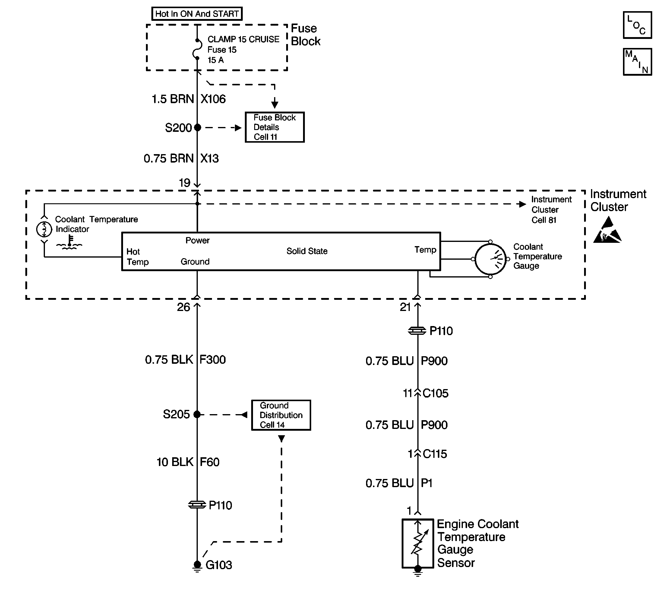
Circuit Description
A microprocessor in the instrument cluster sends voltage to the engine coolant temperature gauge sensor. The gauge sensor is a thermistor, as the temperature of the engine coolant changes the resistance of the gauge sensor changes. The instrument cluster monitors changes in the voltage caused by the changes in the resistance of the sensor to determine coolant temperature.
As the resistance of the gauge sensor decreases, the coolant temperature gauge senses a smaller voltage drop across the gauge sensor indicating higher coolant temperature. As the resistance of the sensor increases, the temperature gauge senses a larger voltage drop across the gauge sensor indicating lower coolant temperature.
Conditions for Setting the DTC
The coolant temperature gauge circuit is tested every 100 ms. DTC 14 will set when the circuit is shorted to ground or the coolant sensor is internally shorted (less than 20 ohms) for more than 8 seconds.
Action Taken When the DTC Sets
- Stores a DTC 14 in memory
- The coolant temperature gauge pointer will return to the zero position
Conditions for Clearing the MIL/DTC
| • | The resistance must be greater than 20 ohms for 4 seconds to clear the fault in the next monitoring cycle |
| • | Conditions for the fault are no longer present |
| • | Using a scan tool. |
Diagnostic Aids
| • | If the DTC is a history or intermittent DTC try performing the test shown while WIGGLING wiring and connectors. This can often cause the malfunction to appear. |
| • | Visually inspect the harness and the harness connectors for the following condition: |
| • | Damage |
| • | Corrosion |
| • | Water intrusion |
| • | Adequate terminal tension |
| • | Mis-routed harness |
| • | Rubbed through wire insulation |
| • | Broken wire inside the insulation |
| • | Before replacing the instrument cluster check all power and ground circuits to the cluster. |
Test Description
The number(s) below refer to the step number(s) on the diagnostic table.
-
This test determines whether the instrument cluster is supplying voltage to the coolant temperature gauge sensor. No voltage may indicate a grounded circuit.
-
After a circuit repair is made, the system is checked again to see if the DTC resets. If the DTC resets, the instrument cluster most likely has an internal failure.
Step | Action | Value(s) | Yes | No |
|---|---|---|---|---|
1 | Was the Instrument Cluster Diagnostic System Check performed? | -- | ||
Is the voltage within the specified range? | B+ | |||
3 | Measure the resistance from connector C105 terminal 11 (sensor side) to ground. Is the resistance 15 ohms or less? | -- | ||
4 |
Is the resistance within the specified range? | OL | ||
5 |
Is the resistance 15 ohms or less? | -- | ||
6 | Move related harnesses and harness connectors while monitoring the DMM. Was a circuit problem found and repaired? | -- | Go to Diagnostic Aids | |
Is a current DTC 14 set? | -- | System OK | ||
8 | Repair the short to ground between the instrument cluster connector terminal 21 and C105 terminal 11 (CKT P900 BLU wire). Is the repair complete? | -- | -- | |
9 | Replace the coolant sensor. Is the replacement complete? | -- | -- | |
10 | Repair the short to ground in the circuit between C105 terminal 11 and C115 terminal 1. Is the repair complete? | -- | -- | |
11 | Replace the instrument cluster. Is the replacement complete? | -- | Go to Instrument Cluster System Check | -- |
