Removal Procedure
- Diable the SIR system. Refer to Disabling the SIR System .
- Open the Instrument Panel (I/P) compartment box.
- Remove the passenger-side I/P access panel
- Remove the passenger-side air deflector.
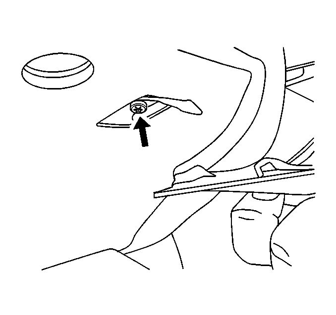
- Lower the module cover screws.
- Remove the four screws from the front I/P compartment.
- Remove the two screws from the side of I/P compartment.
- Disconnect the I/P compartment lamp switch and lamp wiring connections.
- Remove the cool air hose from rear of I/P compartment.
- Remove the I/P compartment from vehicle.

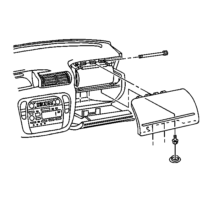
Lift the lower module cover to access two top screws for I/P compartment.
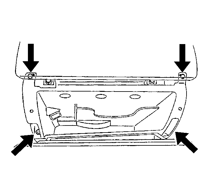
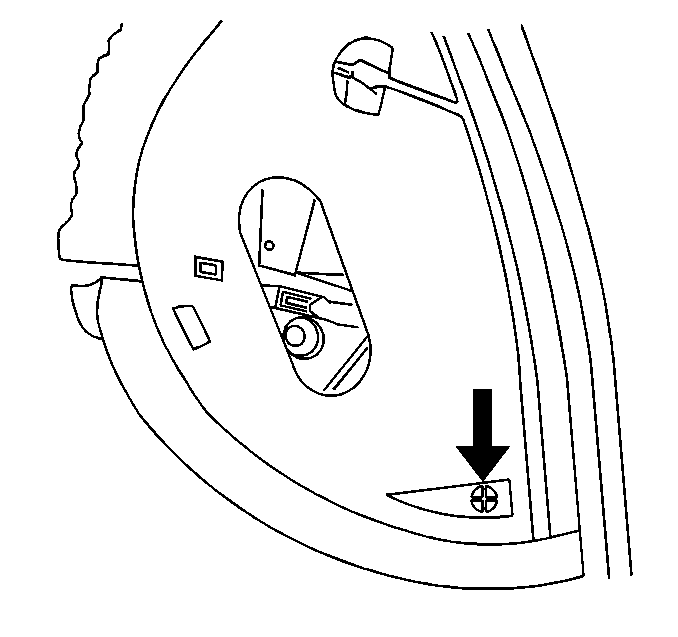
Door Latch Striker Removal Procedure
- Open the Instrument Panel (I/P) compartment door.
- Remove the striker covers.
- Remove the bolts and the strikers from I/P compartment box.
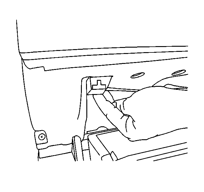
Door Damper Removal Procedure
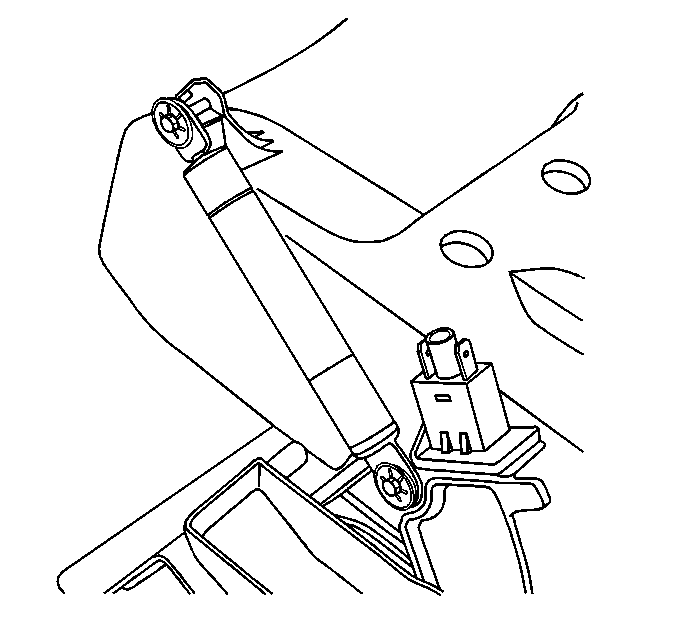
- Remove the compartment damper retainers.
- Remove the compartment damper from housing.
Door Removal Procedure
- Use a punch and a hammer drive out door hinge roll pins.
- Remove the I/P compartment door from instrument panel compartment box.
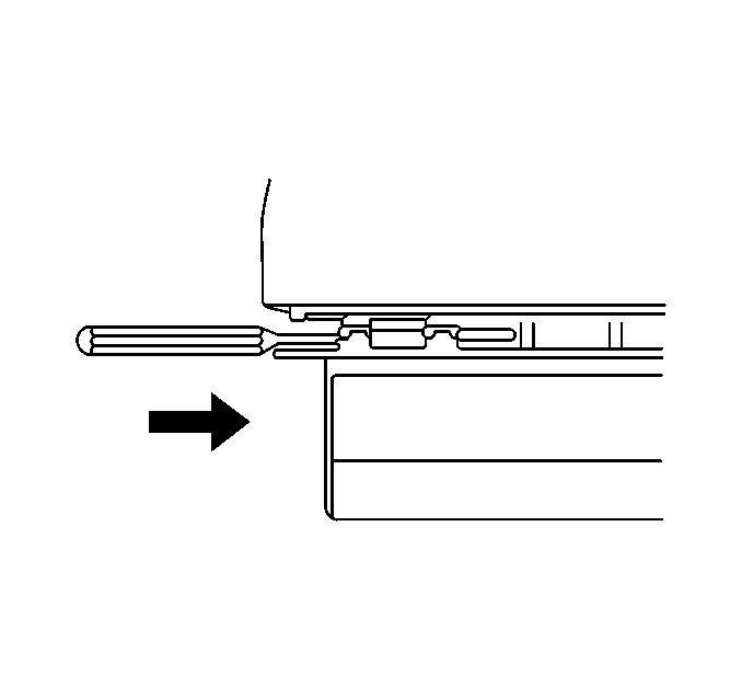

Important: The removal of the compartment door from the guide stops requires care not to break the guide stops as the guide stop on the left side (where damper mounts) is a tight fit when removing.
Door Cover Removal Procedure
- Remove the compartment door inner cover screws.
- Remove the compartment door inner cover from compartment door.
Door Handle Removal Procedure
- Remove the handle retainer from inside handle.
- Remove the handle from door.
Door Lock Cylinder Removal Procedure
- Insert the key into lock cylinder.
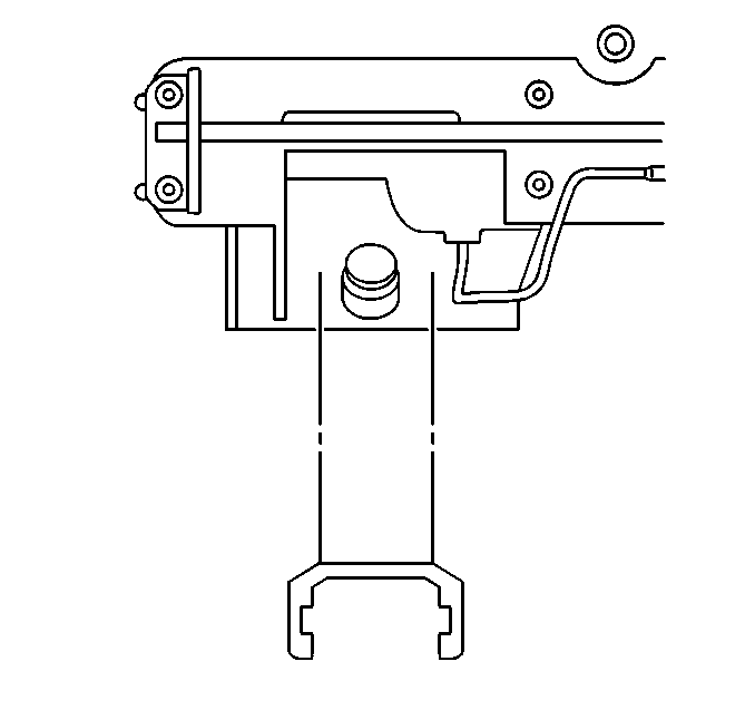
- Unseat retaining tangs from lock cylinder with small screwdriver.
- Gently press cylinder from back side of handle out the front.
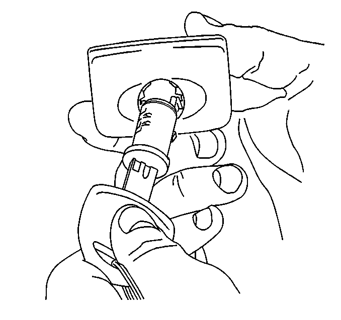
Important: The cylinder tumblers are spring-loaded and if not retained with key they will spring out of cylinder upon removal. If cylinder is not being replaced tape tumblers in place before removing key. For more information on lock cylinder coding procedures refer to Key and Lock Cylinder Coding .
Door Lock Cylinder Installation Procedure
- Gently insert cylinder with key inserted into front of handle until retainer tangs have seated.
- Remove the key.

Important: Verify cylinder installation by applying moderate pressure to back side of cylinder. Cylinder should not move from mounted position.
Door Handle Installation Procedure
- Install the handle to door.
- Install the handle retainer to inside handle.

Door Cover Installation Procedure
- Install the compartment door inner cover to compartment door.
- Install the compartment door inner cover screws.
Tighten
Tighten the compartment door inner cover screws until fully seated but
not stripped. Refer to
Notice: Use the correct fastener in the correct location. Replacement fasteners must be the correct part number for that application. Fasteners requiring replacement or fasteners requiring the use of thread locking compound or sealant are identified in the service procedure. Do not use paints, lubricants, or corrosion inhibitors on fasteners or fastener joint surfaces unless specified. These coatings affect fastener torque and joint clamping force and may damage the fastener. Use the correct tightening sequence and specifications when installing fasteners in order to avoid damage to parts and systems.
.Door Installation Procedure
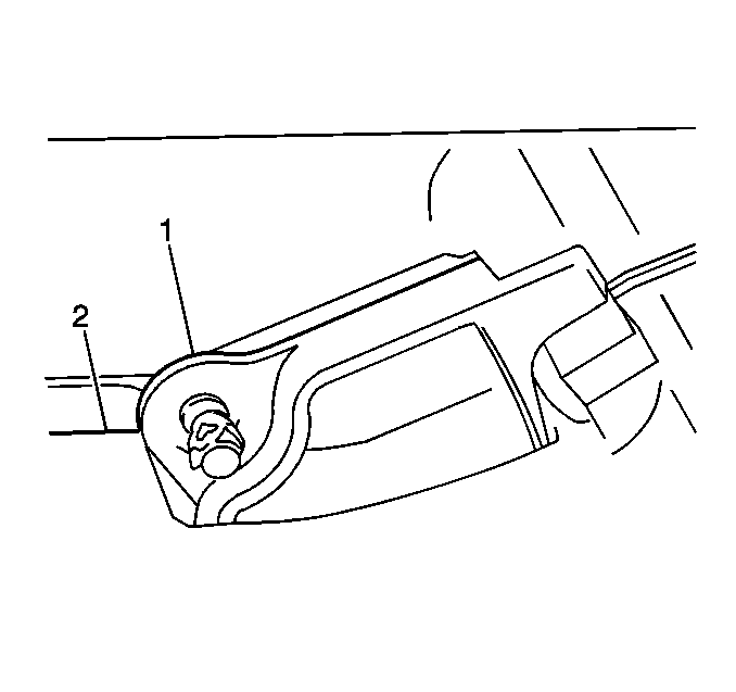
- Install the I/P compartment door to I/P compartment box.
- Using a punch and a hammer drive in door hinge roll pins.

Door Damper Installation Procedure
- Install the compartment damper to housing.
- Install the compartment damper retainer.

Door Latch Striker Installation Procedure
- Install the strikers to I/P compartment box secure with bolts.
- Adjust the strikers to full forward position (with only move about 1/8 in) for proper engagement with latch mechanism.
- Install the striker covers.
- Close the IP compartment door verify to smooth latch engagement. Reposition the strikers until smooth latch engagement is obtained if the IP compartment door requires excessive force to latch.

Tighten
Tighten the bolts until fully seated but not striped.

Installation Procedure
- Install the IP compartment to vehicle.
- Install the cool air hose to rear of IP compartment.
- Connect the IP compartment lamp switch and the lamp wire connectors.
- Install the screws to the front of IP compartment.
- Install the two screws to the side of IP compartment.
- Install the screws to the lower module cover.
- Install the passenger side IP access panel.
- Close the IP compartment door.
- Enable SIR system. Refer to Enabling the SIR System .

Tighten
Tighten the screws until fully seated but not stripped.

Tighten
Tighten the screws until fully seated but not stripped.

Tighten
Tighten the screws to 8 N·m (71 lb in).

