GM Service Manual Online
For 1990-2009 cars only
Makes
🢒
Buick
🢒
1998
🢒
Riviera
🢒
Body and Accessories
🢒
Doors
🢒 Door Lock/Indicator Schematics
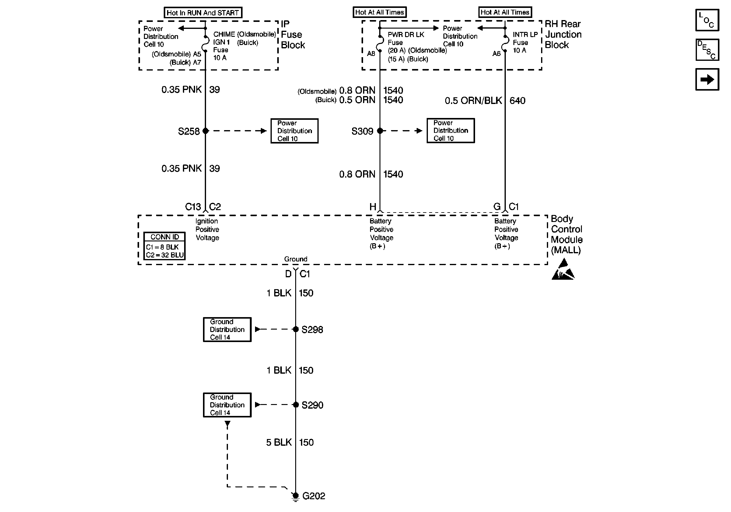
Figure
1:
Cell 130: IP Fuse Block
Cell 10: PWR DR LK and BATT THER Fuses
Cell 10: CHIME (IGN 1) Fuse (Buick)
Cell 14: G202 (1 of 3) (Oldsmobile)
Power Door Systems Connector End Views
Handling ESD Sensitive Parts Notice
Cell 130: Remote Function Actuator (RFA) Module
Cell 14: G202 (1 of 3) (Oldsmobile)
Cell 10: PWR DR LK and BATT THER Fuses
Power Door Locks Circuit Description
Power Door Systems Components
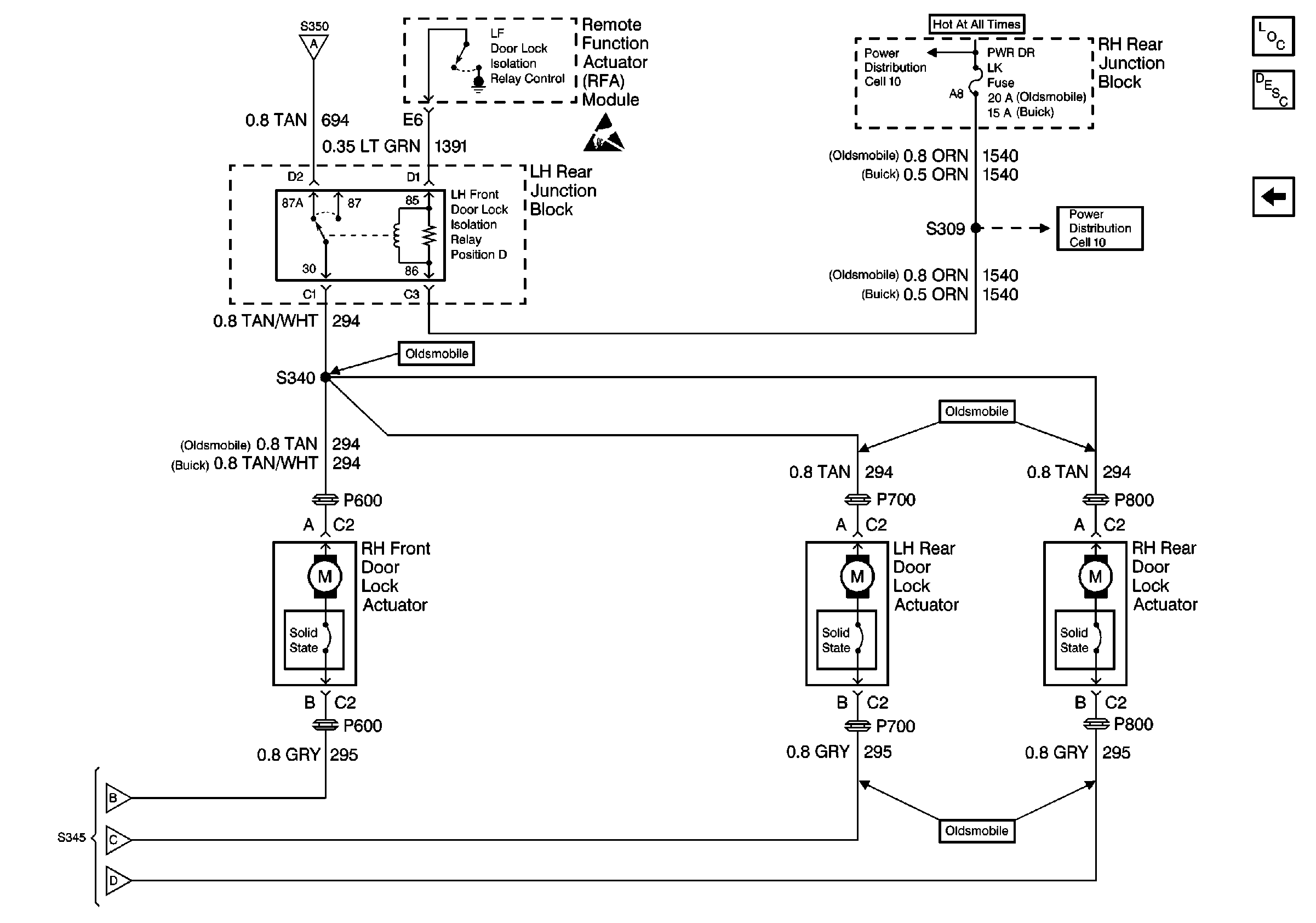
Figure
2:
Cell 130: Remote Function Actuator (RFA) Module
Cell 14: G201 (2 of 2)
Power Door Systems Connector End Views
Handling ESD Sensitive Parts Notice
Cell 130: IP Fuse Block
Cell 130: LH Front Door Lock Actuator
Power Windows Circuit Description
Power Door Systems Components
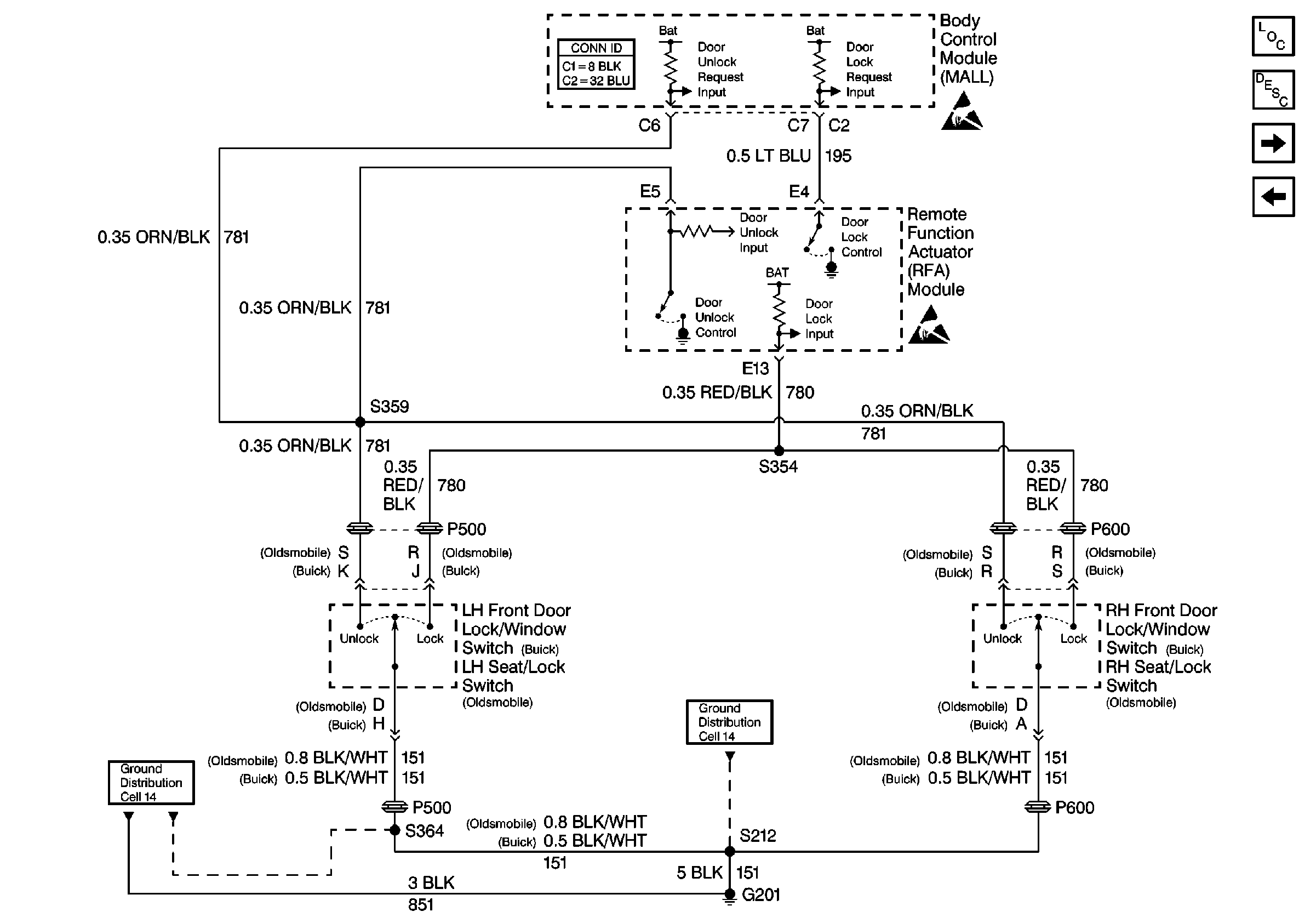
Figure
3:
Cell 130: LH Front Door Lock Actuator
Cell 130: RH Rear Junction Block
Power Door Systems Connector End Views
Handling ESD Sensitive Parts Notice
Cell 130: Remote Function Actuator (RFA) Module
Cell 130: RH Rear Junction Block
Power Door Locks Circuit Description
Power Door Systems Components
Figure
4:
Cell 130: RH Rear Junction Block
Cell 130: LH Front Door Lock Actuator
Cell 10: PWR DR LK and BATT THER Fuses
Handling ESD Sensitive Parts Notice
Cell 10: PWR DR LK and BATT THER Fuses
Cell 130: LH Front Door Lock Actuator
Power Door Systems Components
Power Door Locks Circuit Description
Cell 130: LH Front Door Lock Actuator