For 1990-2009 cars only
Removal Procedure
- Remove the left sound insulator. Refer to Instrument Panel Insulator Panel Replacement - Left Side in Instrument Panel Gauges, and Console.
- Disconnect the 3 electrical connectors.
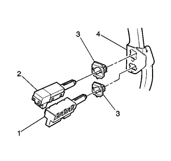
- Remove the following components from the bracket (4):
Notice: Proper stoplamp switch adjustment is essential. Improper stoplamp switch adjustment could cause brake drag and excessive brake lining wear.

| • | The brake transmission shift interlock (BTSI) switch assembly (1) |
| • | The stoplamp switch assembly (2) |
Installation Procedure
- Install the following components through the bracket (4):
- Connect the 3 electrical connectors.
- Adjust the switch. Refer to Brake Release Switch Adjustment .
- Install the left sound insulator. Refer to Instrument Panel Insulator Panel Replacement - Left Side in Instrument Panel Gauges, and Console.

| • | The BTSI switch assembly (1) |
| • | The stoplamp switch assembly (2) |
