Tools Required
J 39400-A Halogen Leak Detector
Removal Procedure
- Recover the refrigerant. Refer to Refrigerant Recovery and Recharging .
- Remove left headlamp. Refer to Headlamp Assembly or Headlamp Bulb and/or Cornering, Sidemarker, Park, Turn Signal Bulb Replacement in Lighting Systems.
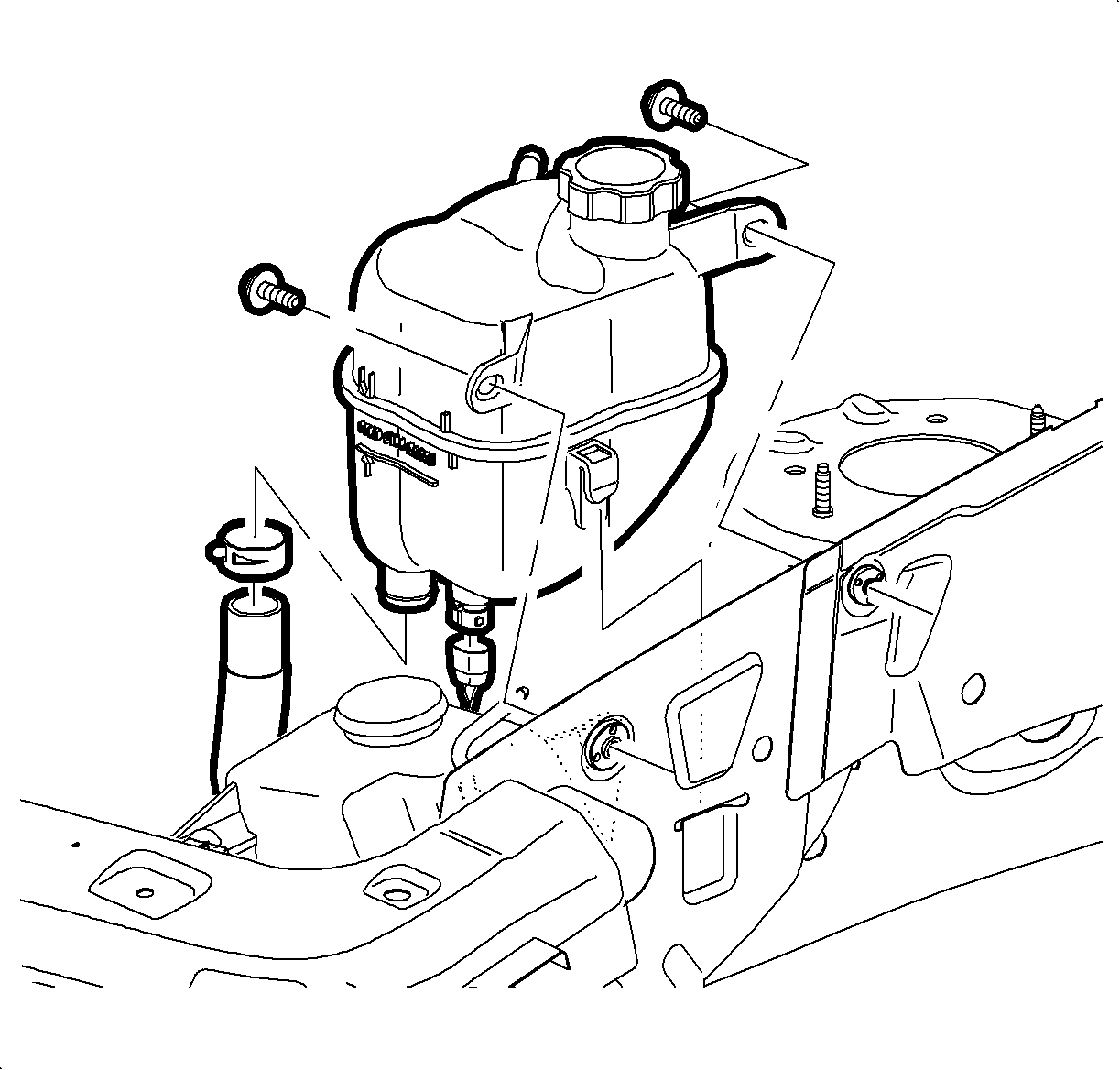
- Remove surge tank to upper motor rail fasteners.
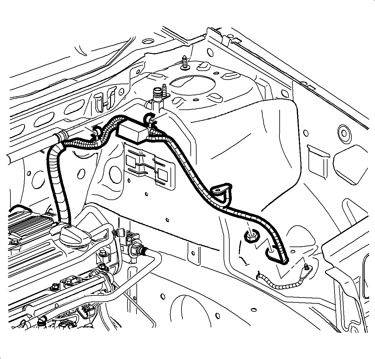
- Unclip EPS harness from liquid line.
- Unclip PTU vent from liquid line.
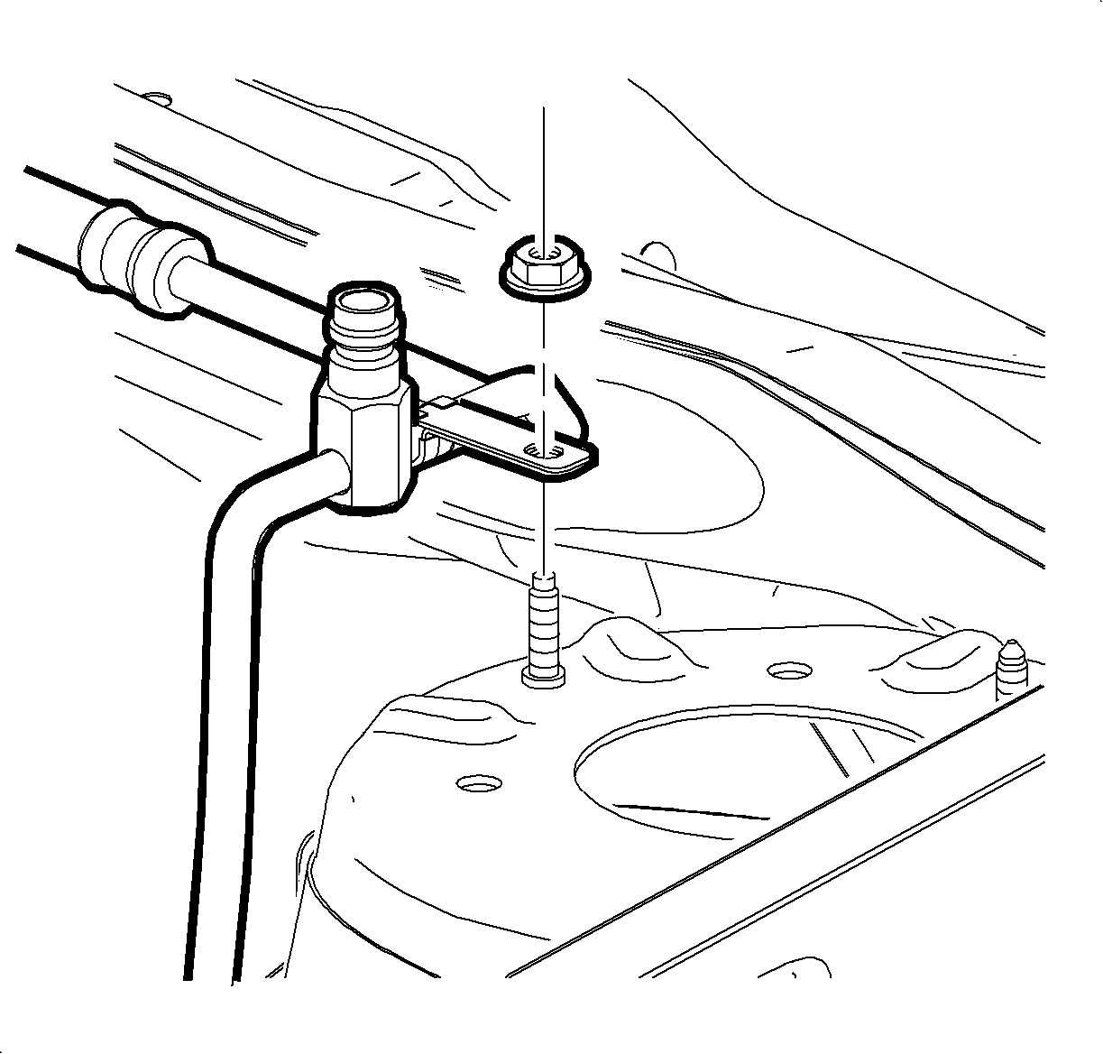
- Remove nut from P-clip at shock tower cap stud.
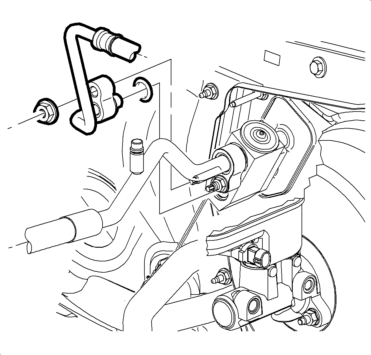
- Remove liquid line to TXV nut.
- Remove liquid line to receiver/dehydrator (RD) nut. Use a large pair of pliers to hold fitting to prevent twisting of line if necessary.
- Remove liquid line at left shock tower and install protective caps to RD and TXV to prevent contamination and desiccant saturation.
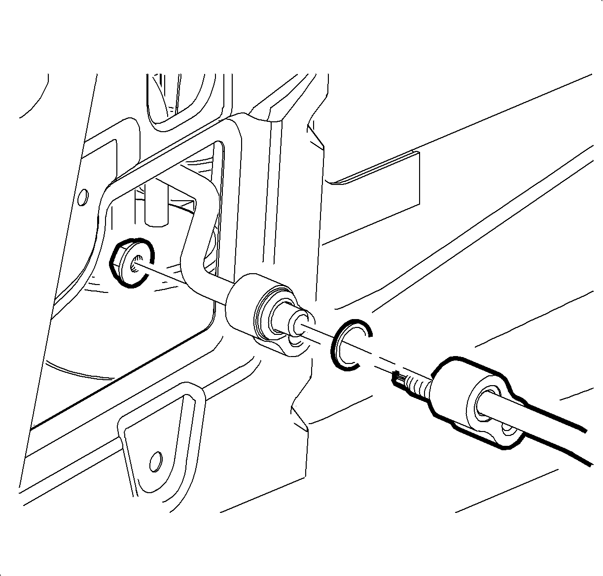
Installation Procedure
- Remove protective cap from RD and RD end of liquid line and install new seal washer. Refer to Sealing Washer Replacement .
- Feed RD end of liquid line down front of shock tower, beneath the surge return hose and under negative battery cable and battery box.
- From headlamp opening guide RD end of liquid line to RD fitting and install nut.
- Install liquid line nut using a large pair of pliers hold fitting while tightening. Be careful not to twist line.
- Remove protective cap from TXV and TXV end of liquid line, install new seal washers. Refer to Sealing Washer Replacement .
- Install liquid line to TXV with nut.
- Install liquid line P-clip and nut to the shock tower cap stud.
- Clip EPS harness to liquid line.
- Clip PTU vent hose to liquid line.
- Install surge tank and bolts.
- Install left headlamp. Refer to Headlamp Assembly or Headlamp Bulb and/or Cornering, Sidemarker, Park, Turn Signal Bulb Replacement in Lighting Systems.
- Evacuate and charge the refrigerant system. Refer to Refrigerant Recovery and Recharging .
- Leak test the fittings using the J 39400-A .

Notice: Use the correct fastener in the correct location. Replacement fasteners must be the correct part number for that application. Fasteners requiring replacement or fasteners requiring the use of thread locking compound or sealant are identified in the service procedure. Do not use paints, lubricants, or corrosion inhibitors on fasteners or fastener joint surfaces unless specified. These coatings affect fastener torque and joint clamping force and may damage the fastener. Use the correct tightening sequence and specifications when installing fasteners in order to avoid damage to parts and systems.
Tighten
Tighten the nut to 16 N·m (12 lb ft).

Tighten
Tighten the nut to 16 N·m (12 lb ft).

Tighten
Tighten the nut to 8 N·m (71 lb in).


Tighten
Tighten the bolt to 6 N·m (53 lb in).
