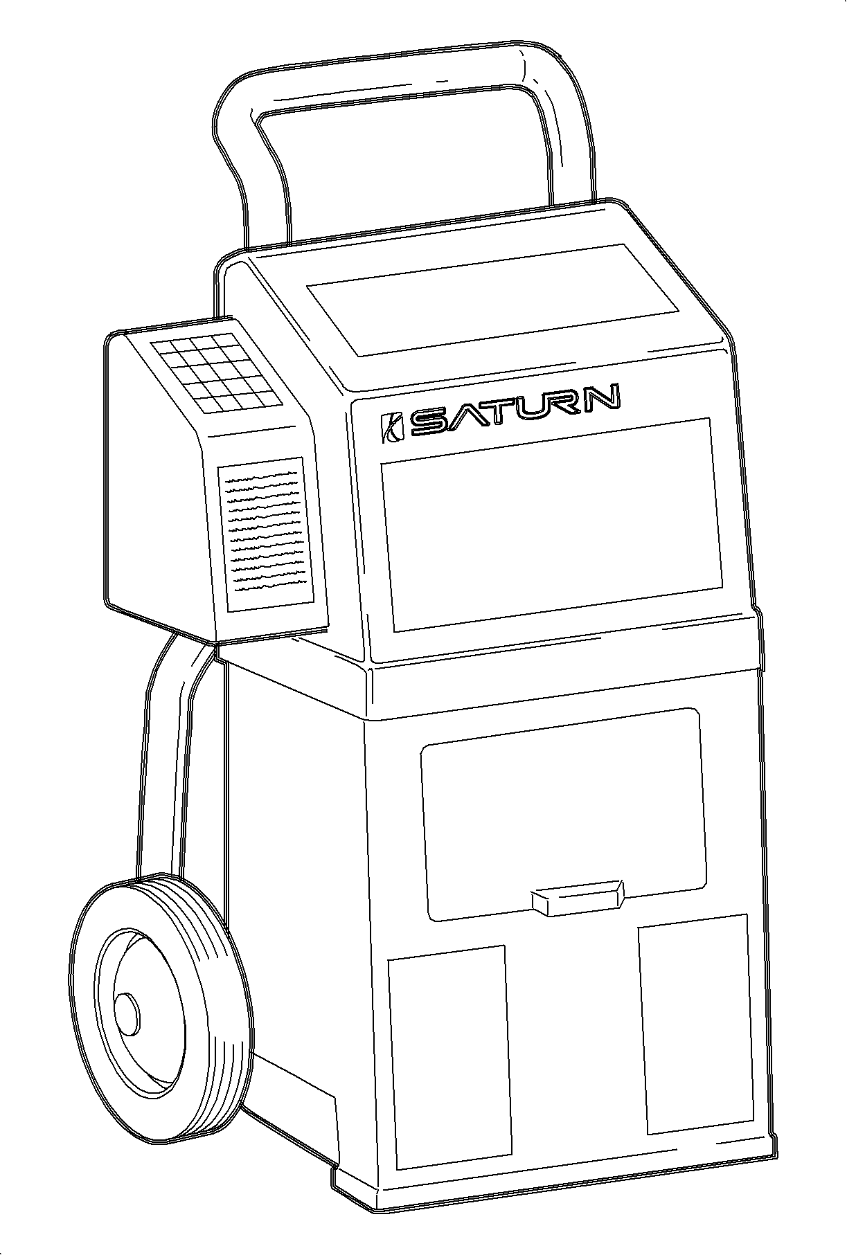
Identifying Refrigerant Purity
- Turn ON refrigerant identifier and let it reach operating temperature (3-5 minutes).
- When display reads "HOSE," and with the vehicle turned OFF, attach the hose to the low side (suction) port and open service valves.
- Press ENTER button.
- The display will read GAS as a sample of refrigerant is taken and analyzed.
- When analysis is complete, display will show, by percentage, the make-up of gases.

Notice: The purity of the system refrigerant should be confirmed before any other diagnostics are begun. The RI-2002DS refrigerant identifier has the ability to identify R-12, R134a, R-22, potentially dangerous hydrocarbons, and non-condensable gases (NCG) such as air. If the A/C system contains anything less than 98 percent pure refrigerant, the refrigerant is considered contaminated and the temperature/pressure charts will not be valid. Contaminated refrigerant should not be recovered as it will contaminate the recovery machine and refrigerant supply tank. Air is not considered a contaminate as it can be purged.
| • | If refrigerant is less than 98 percent pure, the temperature/pressure charts will not be accurate for system diagnosis. |
| • | If refrigerant is pure but contains air, system should be recovered and recharged with virgin refrigerant before proceeding. |
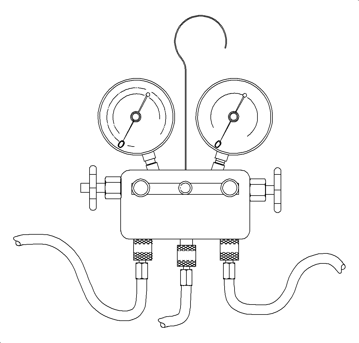
Installing Manifold Gage Set

If an A/C system problem still exists after you have completed the preliminary inspects, more diagnostic tests must follow. These include manifold gage set readings. Follow the steps listed below for installing a manifold gage set.
- Close both hand valves of manifold gage set.
- Connect low pressure (blue) gage hose to suction service port located on the suction pipe. Pull valve assembly collar up, place valve assembly over service port and release collar.
- Open service valve.
- Connect high pressure (red) gage hose to discharge service port located on the liquid line. Pull valve assembly collar up, place valve assembly over service port and release collar.
- Open service valve.
Caution: Always wear goggles and wrap a clean cloth around fittings, valves, and connections when performing work that involves opening the refrigerant system.
Important: Inspect to make sure gages read zero before installing manifold gage set.
Performance Test - Service Stall
- Open hood and leave open during entire test.
- Install a manifold gage set to high and low side service ports.
- Disconnect vehicle thermal expansion valve (TXV) temperature sensor electrical connector and connect a temperature sensor that is exposed to ambient air.
- Start engine and warm to operating temperature. Use scan tool to verify coolant temperature is being thermostatically controlled approx. 88°C (190°F).
- Install thermometer into right center outlet.
- Open both front doors and windows to stabilize interior air temperature with outside ambient temperature.
- Press re-circulation button so that indicator light is lit.
- Set temperature knob to full cold position.
- Set mode knob to I/P outlet position.
- Set blower to third speed.
- Press A/C button.
- Using Tech 2, command fan to HIGH speed.
- Using accelerator pedal, increase engine speed to 2,000 RPM and hold.
- Continue running until system pressures and outlet temperature stabilizes. Usually 4 to 8 minutes.
- Record A/C system pressures and outlet temperature every minute for five minutes.
- Exit out of the scan tool test and return engine to idle.
- Release Tech 2 control of engine cooling fans.
- Compare recorded values to system performance charts then continue down diagnostic flow chart.
- When test is complete, re-connect the electrical connector for the vehicle TXV temperature sensor.
Important: If ambient air temperature is lower than 0° C (32° F), A/C compressor will not be enabled.
Important: This test must be performed in a service stall environment that protects the vehicle from wind that could cause incorrect pressure/temperature readings.
