Special Tools
| • | J 41556 Connecting Rod Guide
|
| • | J 43654 Piston Pin Clip Remover and Installer
|
| • | J 43690 Rod Bearing Clearance Checking Tool |
| • | J 43690-100 Rod Bearing Clearance Checking Tool-Adapter Kit
|
For equivalent regional tools, refer to
Tools and Equipment.
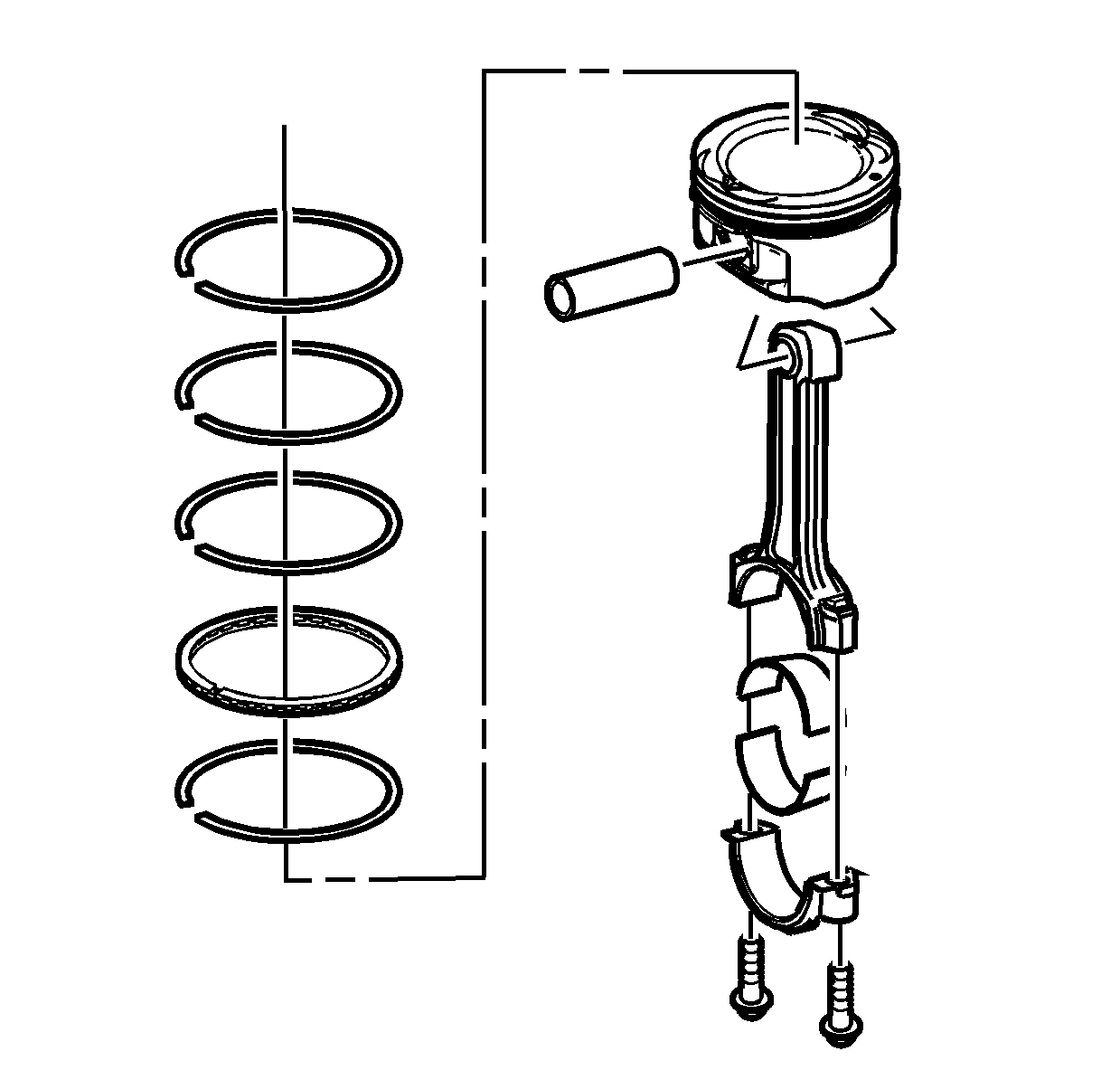
- Lightly lubricate the following components with clean engine oil:
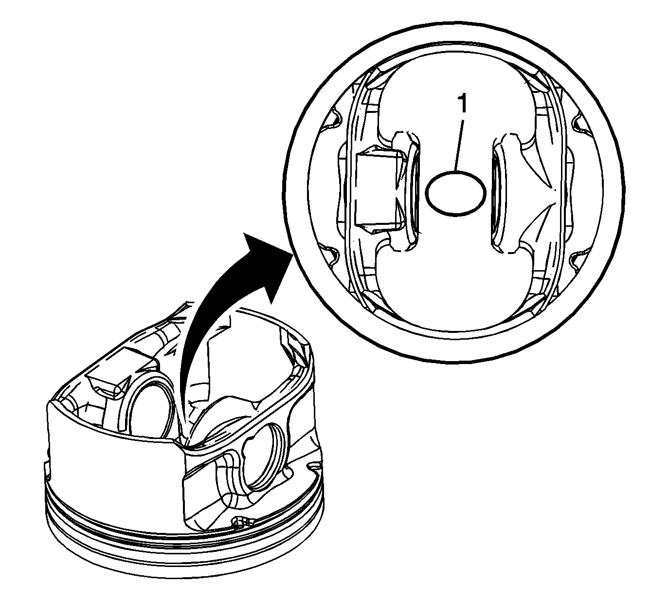
- There are two styles of pistons in use in the LZ engine, and each piston must use the appropriate matching piston ring set. To identify which make you have, look on the bottom of the piston, in between the piston pin bores.
| • | If there is an "FM" marking, it is a Federal Mogul piston and must use the Federal Mogul piston rings. |
| • | If there is no marking, it is a Mahle piston and must use Mahle piston rings. Failure to do so may result in engine damage. |
Note: The tops of the first and second piston rings are marked with light green stripes to insure proper orientation on the piston. The top ring has a light green stripe 180 degrees from the gap, and the second ring has a light
green stripe 90 degrees from the gap. These stripes must be facing up and in this orientation prior to installing the pistons. This is necessary for proper operation.
- Stagger the oil control ring end gaps a minimum of 90 degrees.
- Stagger the compression ring end gaps a minimum of 25 mm (1 in).
- Install the
J 8037 compressor
onto the piston and compress the piston rings.
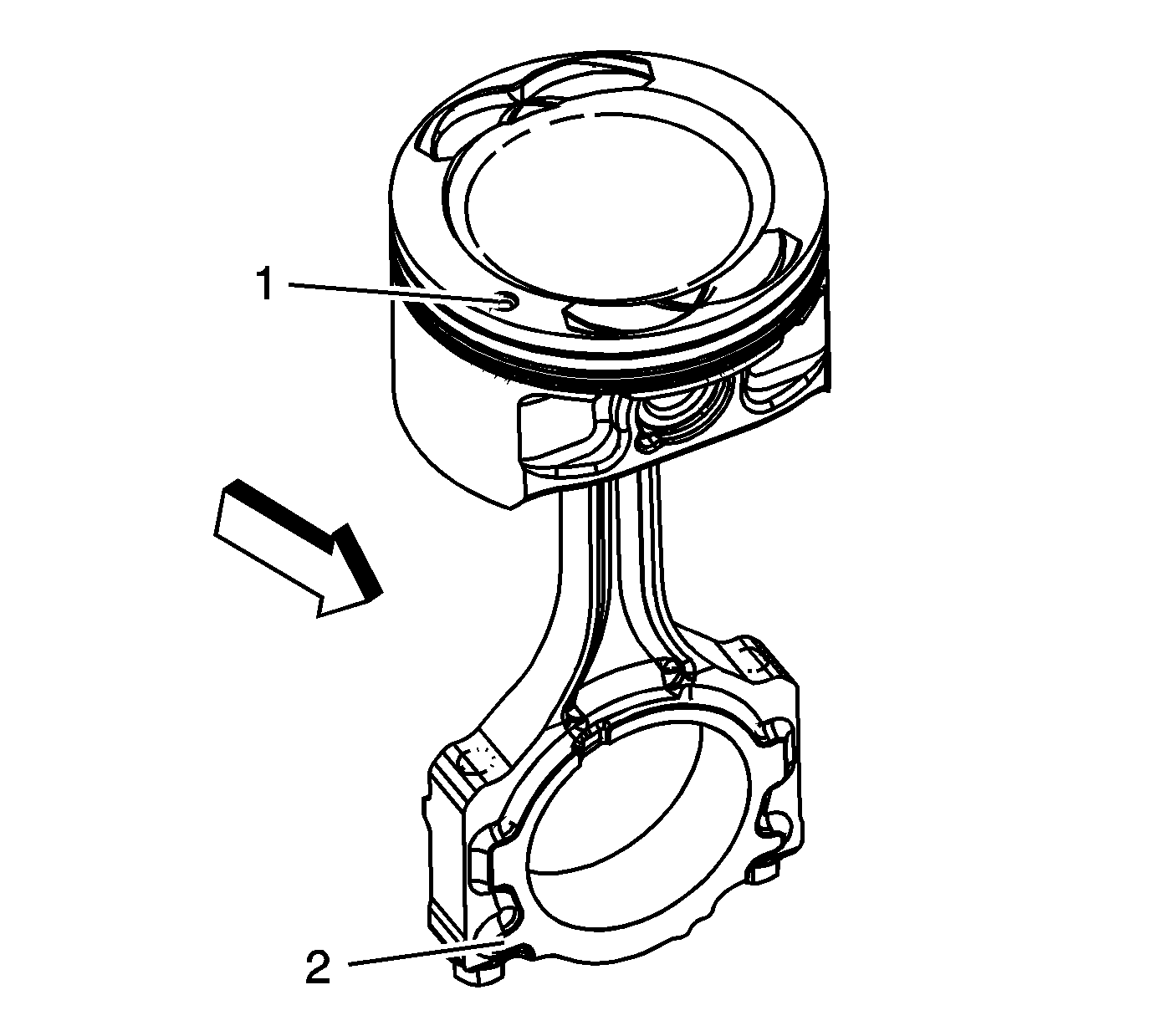
Note: When assembling the connecting rod to the piston, make sure the connecting rod reference mark (2) is facing towards front of engine, and is in proper correlation with the front of engine piston reference mark (1).
- Align the piston pin bore with the connecting rod pin bore.
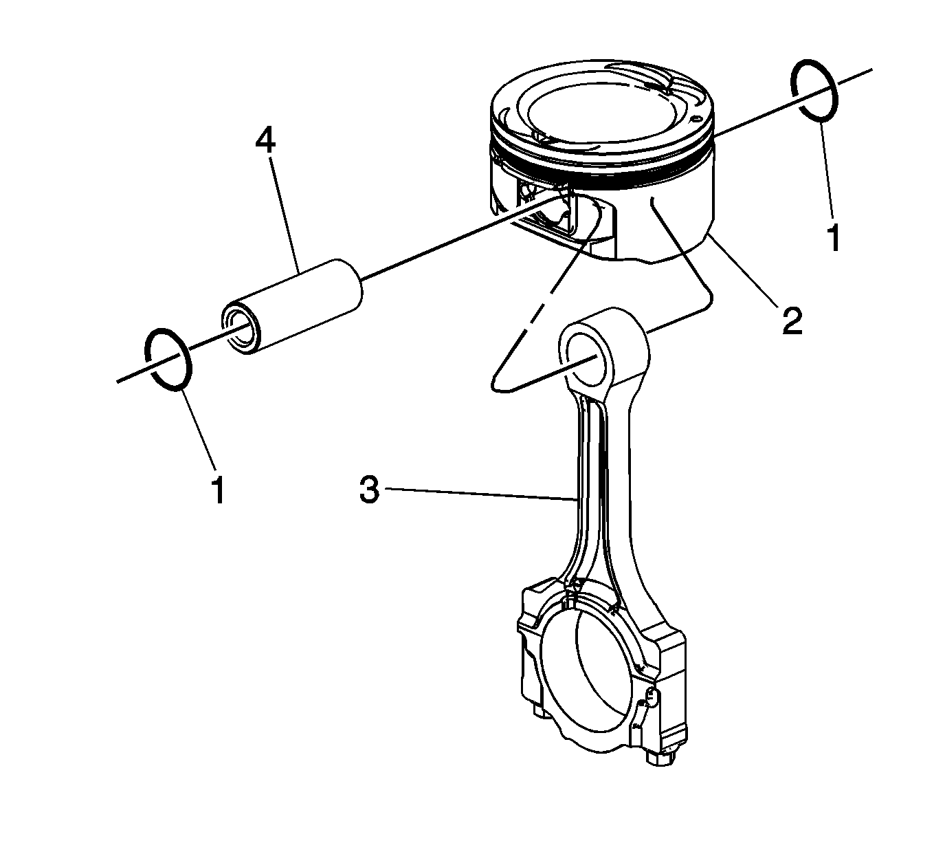
- Slide the piston pin (4) into the piston and the connecting rod (3).
Note: NEW piston pin retainers must be used. Never reuse the piston pin retainers.
- Install NEW piston pin retainers (1) using the
J 43654 installer
.
- Ensure that the piston pin retainers are fully seated in their grooves.
- Repeat these procedures for the remaining pistons.
- Install the
J 41556 guide
into the connecting rod.
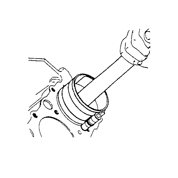
- Install the piston and connecting rod assembly into the proper cylinder bore.
- Hold the piston ring compressor firmly against the engine block. Using a wooden hammer handle, lightly tap the top of the piston until all of the piston rings enter the cylinder bore.
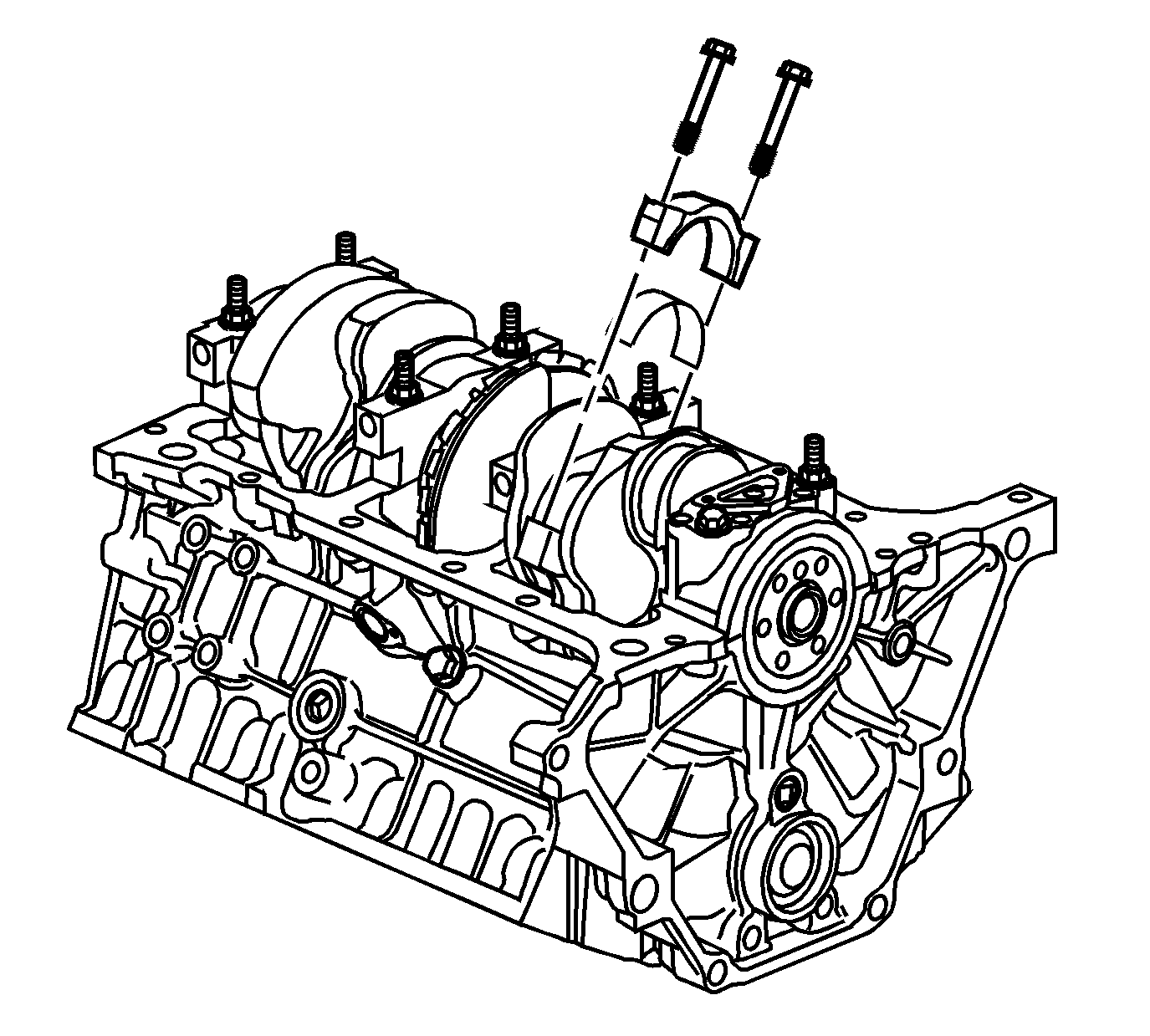
Note: When installing the pistons into the cylinder bore, make sure not to contact the piston oil nozzle with the connecting rod. Failure to do so may damage the piston oil nozzle, resulting in potential engine damage.
- Using
J 41556 guide
, guide the connecting rod end onto the crankshaft journal.
Caution: Refer to Fastener Caution in the Preface section.
- Install the bearing, bearing cap and bolts.
| • | Tighten the connecting rod bearing cap bolts a first pass to
25 N·m (18 lb ft). |
| • | Tighten the connecting rod bearing cap bolts a final pass to
110 degrees using the
J 45059 meter
. |
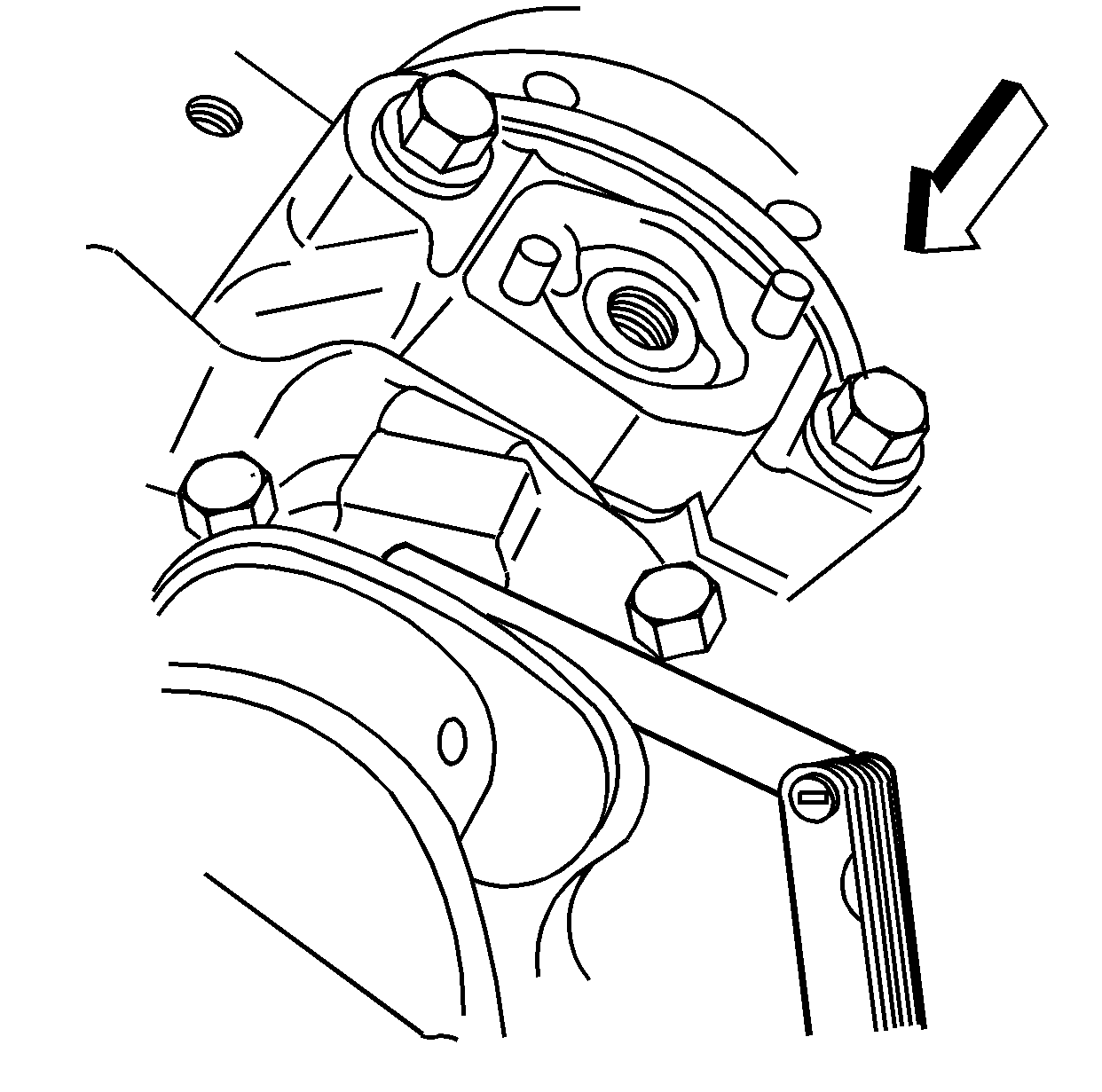
- With the pistons and connecting rods installed, use a soft faced mallet and lightly tap each connecting rod assembly parallel to the crankpin to make sure that the rods have side clearance.
- Measure the connecting rod side clearance using a feeler gage or dial indicator. Connecting rod side clearance should be within 0.18-0.44 mm (0.007-0.017 in).
Measuring Connecting Rod Bearing Clearance Using J 43690 and J 43690-100
J 43690 tool
and
J 43690-100 kit
have been developed as a more accurate method to measure connecting rod bearing clearances.
The instructions below provide an overview of tool set and usage. For more detailed information, refer to the tool instruction sheets as supplied by the tool manufacturer.
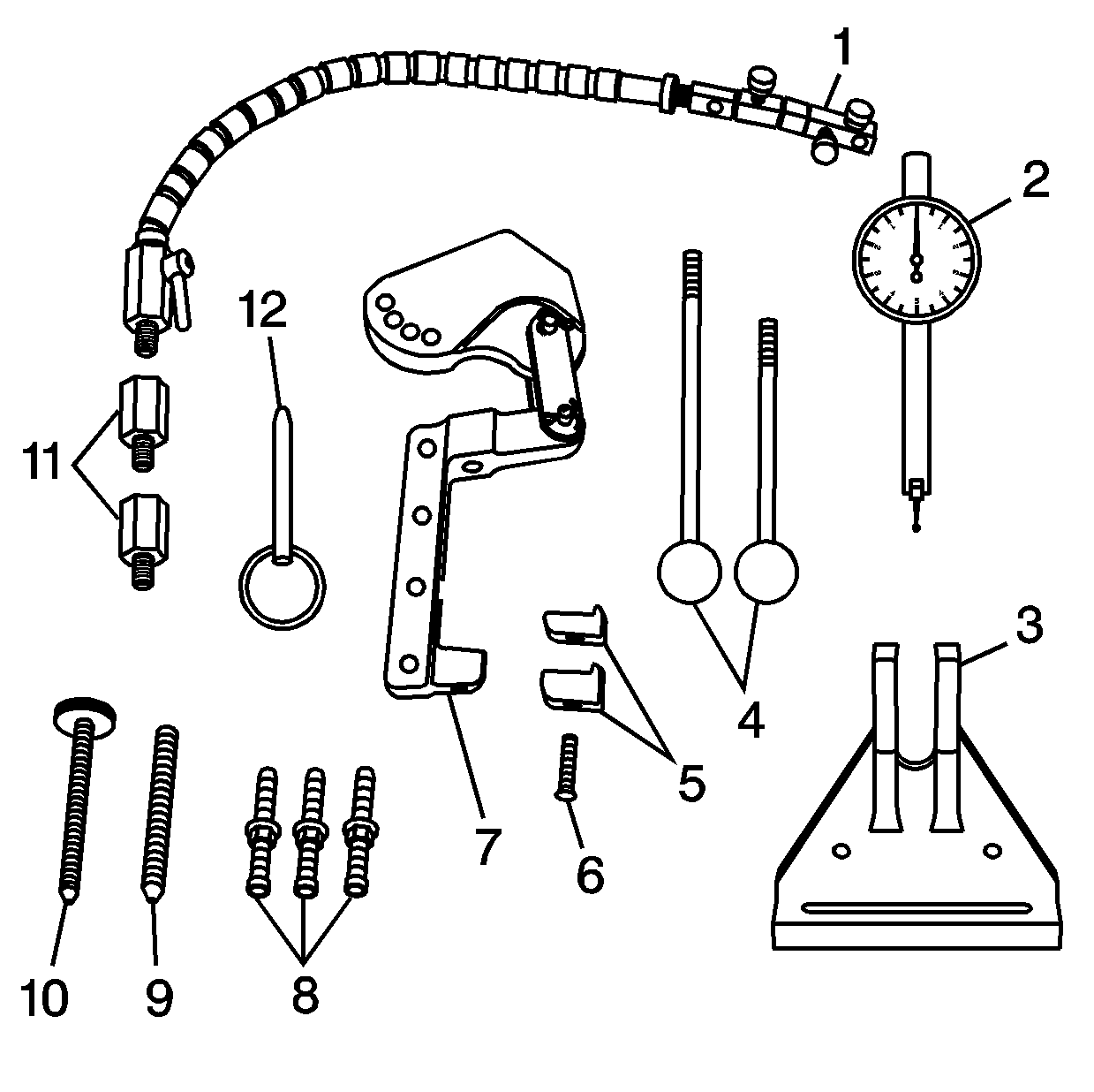
- J 43690 tool
includes:
| • | J 43690-20 Swivel Base (1) |
| • | J 43690-19 Dial Indicator (2) |
| • | J 43690-5,-6 Handle (4) |
| • | J 43690-10,-11 Foot (5) |
| • | J 43690-1 Pivot Arm Assembly (7) |
| • | J 43690-3,-7,-8 Screws (8) |
| • | J 43690-17,-18 Adapter (11) |
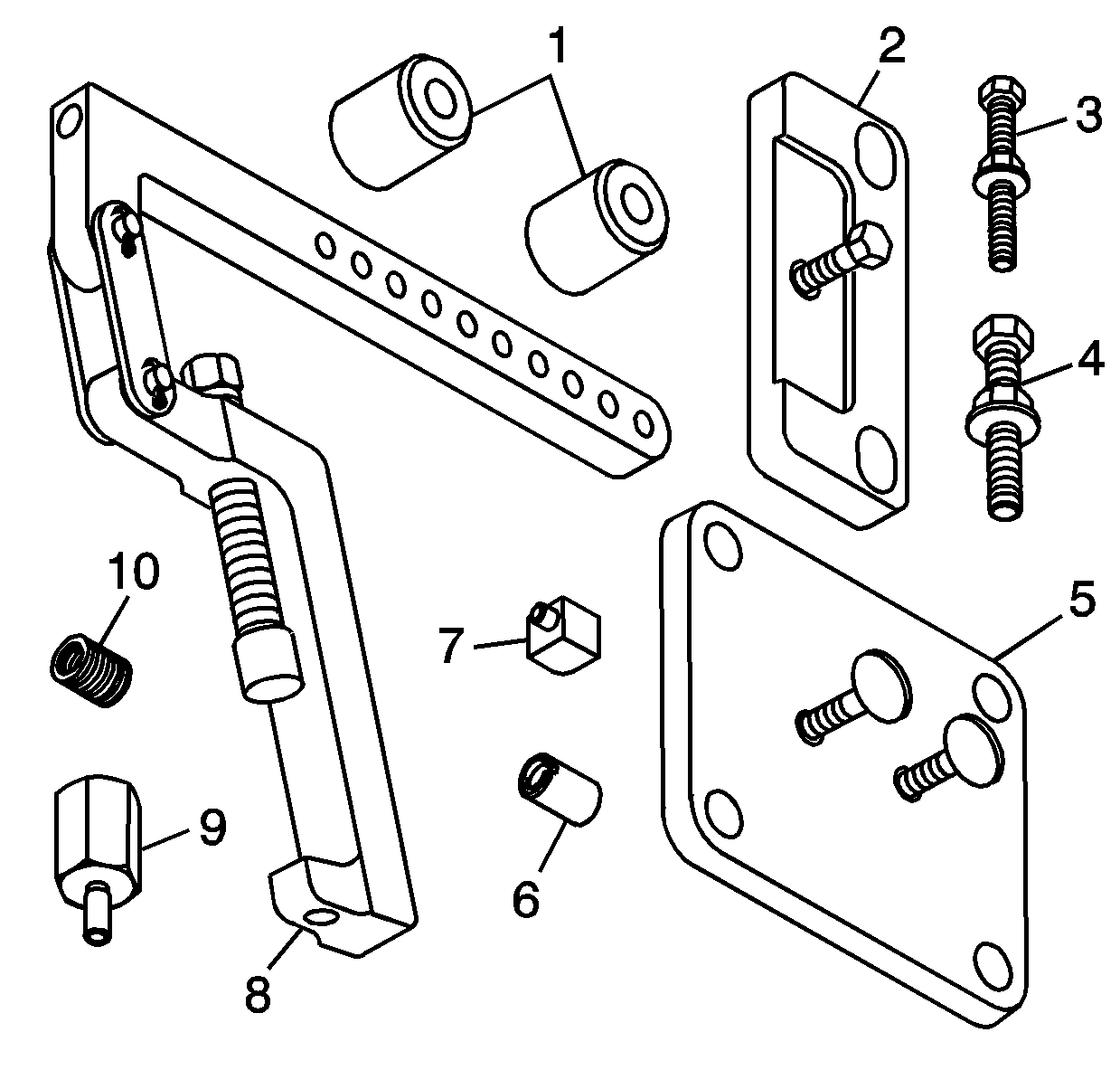
- J 43690-100 kit
Rod Bearing Checking Tool - Adapter Kit includes:
| • | J 43690-105 Retainer Plate (2) |
| • | J 43690-106 Retainer Plate (5) |
| • | J 43690-101 Pivot Arm Assembly (8) |
| • | J 43690-103 Adapter (9) |
Note: The crankshaft must be secure with no movement or rotation in order to obtain an accurate reading.
- Rotate the crankshaft until the journal/connecting rod to be measured is in the 12 o'clock position.
- Remove the crankshaft main bearing cap bolts.
- Remove the crankshaft main lower bearing cap.
- Insert a piece of paper stock onto the crankshaft journal.
Caution: In order to prevent the possibility of cylinder block or crankshaft bearing cap damage, the crankshaft bearing caps are tapped into the cylinder block cavity using a brass, lead, or a leather
mallet before the attaching bolts are installed. Do not use attaching bolts to pull the crankshaft bearing caps into the seats. Failure to use this process may damage a cylinder block or a bearing cap.
Caution: This bolt is designed to permanently stretch when tightened, and therefore MUST be replaced anytime it is removed. The correct part number fastener must be used to replace this type of fastener.
Do not use a bolt that is stronger in this application. If the correct bolt is not used, the parts will not be tightened correctly. The system or the components may be damaged.
- Install the crankshaft main bearing cap and bolts. Start the crankshaft main bearing cap bolts by hand. Ensure the bottom of the crankshaft main bearing cap is parallel to the bottom of the channel.
| • | Tighten the crankshaft main bearing cap bolts in equal increments. Do not completely tighten one bolt at a time to prevent the cap from being cocked. |
| • | Tighten the bolts to
50 N·m (37 lb ft) to fully seat the crankshaft main bearing caps. Loosen the bolts 360 degrees counterclockwise. |
| • | Tighten the bolts to
20 N·m (15 lb ft), then
50 N·m (37 lb ft). |
| • | Use
J 45059 meter
to tighten the bolts to
77 degrees. |
- Install the following:
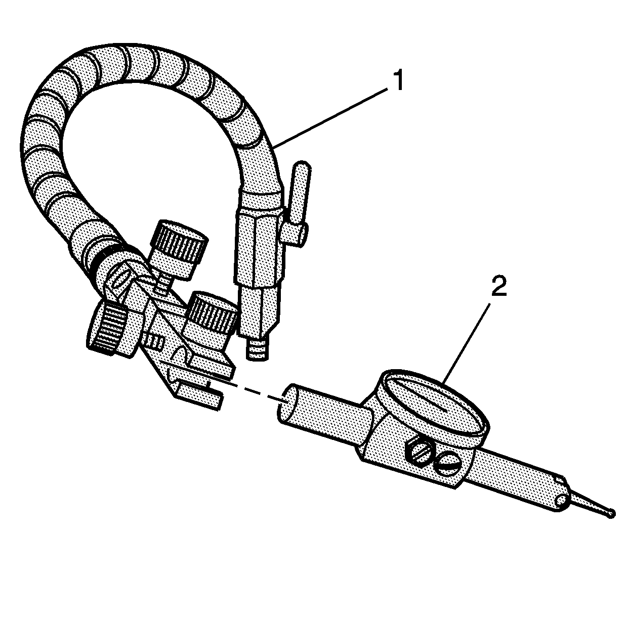
- Install the swivel base (1) and dial indicator (2).
- Adjust per the manufacturers instructions and measure the connecting rod bearing clearance. The connecting rod bearing clearance should be between 0.0127-0.0660 mm (0.0005-0.0026 in).


