Special Tools
J-45059 Angle Meter
For equivalent regional tools, refer to Special Tools
- Dip the crankshaft bearing cap bolts in clean engine oil.
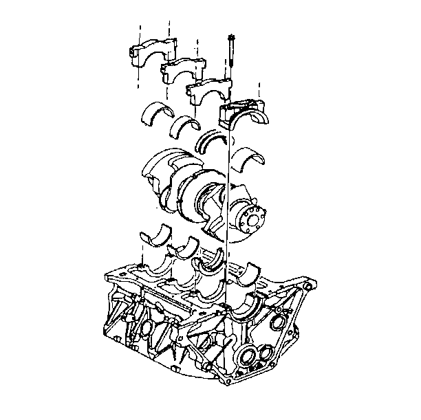
- Place the crankshaft bearing inserts into the crankshaft bearing cap and into the engine block.
- Lubricate the crankshaft main bearing surface with clean engine oil.
- Install the crankshaft.
- Install the crankshaft main bearing caps. Apply a small amount of sealer GM P/N 1052942 (Canadian P/N 10953466) to the rear of the #4 crankshaft main bearing cap sealing surface.
- Install the crankshaft main bearing cap bolts. Use the J-45059 Angle Meter in order to tighten the crankshaft main bearing cap bolts to 50 N·m (37 lb ft) plus 77 degrees.
- Measure the crankshaft end play.
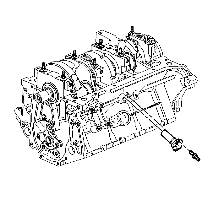
- Install the crankshaft position sensor into the side of the engine block.
- Apply threadlock GM P/N 12345382 (Canadian P/N 10953489) or the equivalent to the crankshaft position sensor stud threads.
- Install the crankshaft position sensor stud and tighten to 11 N·m (98 lb in).
- Install the crankshaft position sensor shield and nut and tighten to 11 N·m (98 lb in).

Note: Ensure that the crankshaft bearing cap bolt holes and the crankshaft bearing cap mating surfaces are clean and dry.
Caution: Upper and lower inserts may be different. Do not obstruct any oil passages.
Note: The crankshaft bearing inserts will project slightly when put into place. Ensure that the bearing inserts project an equal distance on both sides. Ensure that the insert tangs are engaged.
Caution: In order to prevent the possibility of cylinder block or crankshaft bearing cap damage, the crankshaft bearing caps are tapped into the cylinder block cavity using a brass, lead, or a leather mallet before the attaching bolts are installed. Do not use attaching bolts to pull the crankshaft bearing caps into the seats. Failure to use this process may damage a cylinder block or a bearing cap.
Caution: Refer to Fastener Caution in the Preface section.

| 7.1. | Thrust the crankshaft forward or rearward. |
| 7.2. | Insert a feeler gage between the number 3 crankshaft bearing and the bearing surface of the crankshaft and measure the bearing clearance. The proper crankshaft end play clearance is 0.06-0.21 mm (0.002-0.008 in). |
| 7.3. | If the bearing clearance is not within specifications, inspect the thrust surfaces for nicks, gouges or raised metal. Minor imperfections may be removed with a fine stone. |

