GM Service Manual Online
For 1990-2009 cars only
Makes
🢒
Saturn
🢒
2006
🢒
VUE - AWD
🢒
Vehicle Control Systems
🢒
Vehicle DTC Information
🢒 Antilock Brake System Schematics
Figure
1:
Power and Ground
Master Electrical Component List
ABS Description and Operation
Control Module References
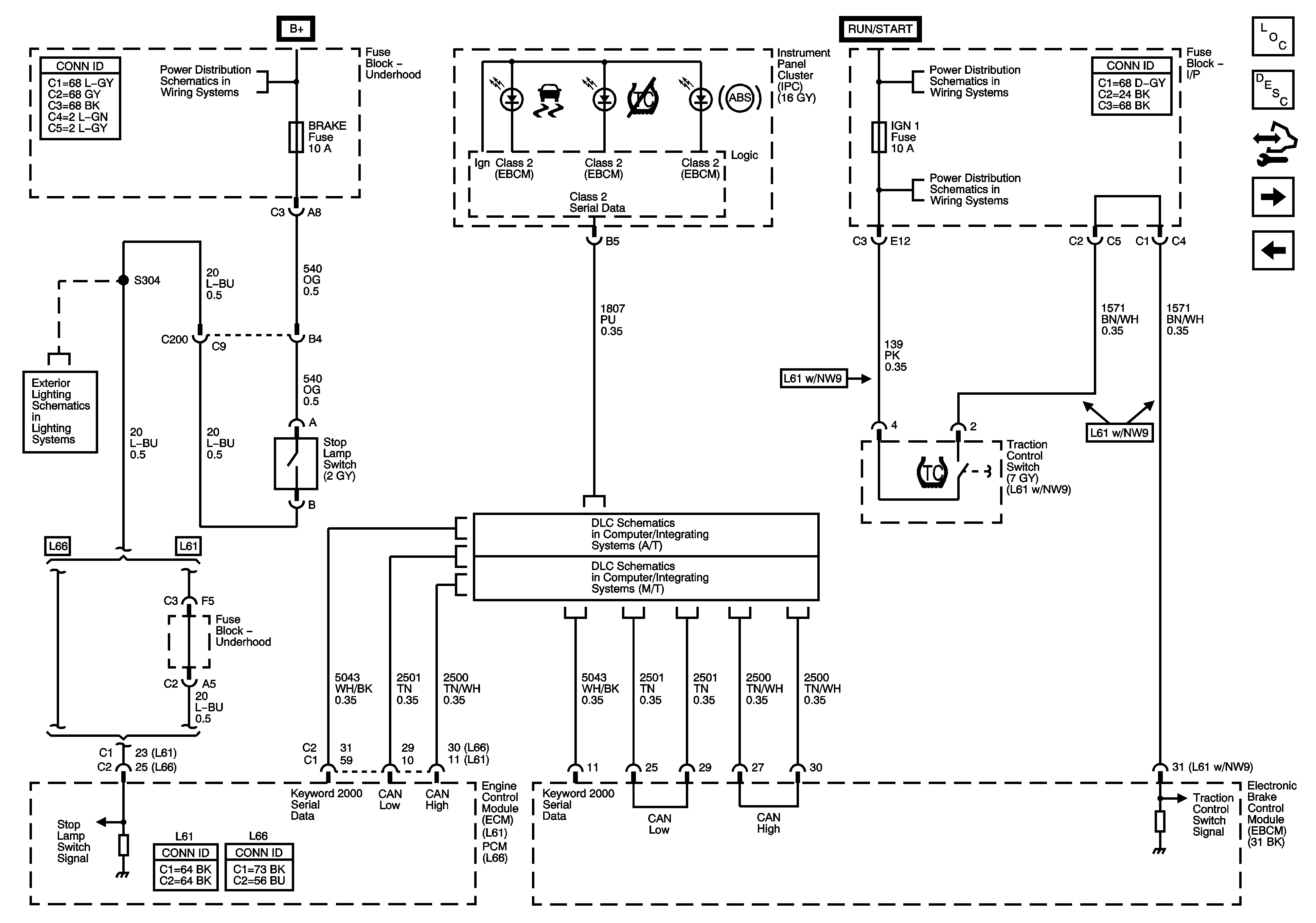
TC Switch, Indicators and the Stop Lamp Switch Signal
SUNROOF Fuse, PWR WDW Fuse, 10A ABS Fuse, 20A ABS Fuse, ABS PWR Fuse, HVAC BLOWER Fuse, AUX1 OUTLET Fuse, CIGAR/AUX2 Fuse and the ECM/TCM Fuse
B+ Bussing and the EPS Fuse
Figure
2:
TC Switch, Indicators and the Stop Lamp Switch Signal
Master Electrical Component List
ABS Description and Operation
Control Module References
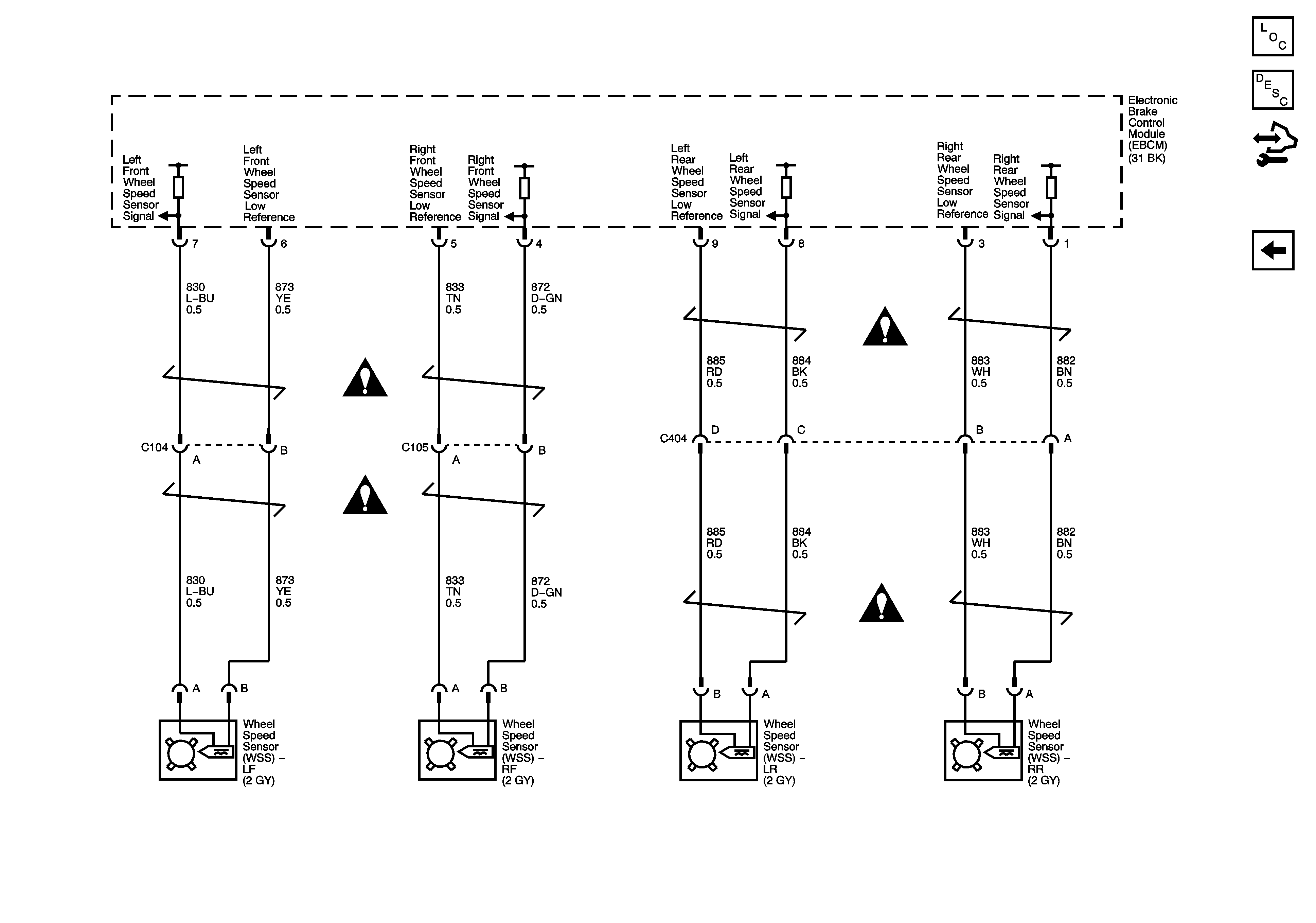
Wheel Speed Sensors
Power and Ground
B+ Bussing and the EPS Fuse
IGN Fuse and the Ignition Switch Circuits
IGN1 Fuse, BCM(IGN) Fuse, AIR BAG Fuse, EPS Fuse and the CRUISE Fuse
Stop Lamps
L66
DLC Schematic (M/T)
Figure
3:
Wheel Speed Sensors
Master Electrical Component List
ABS Description and Operation
Control Module References
TC Switch, Indicators and the Stop Lamp Switch Signal
Antilock Brake System Schematic Icons