Service Manual Information for Automatic Transaxle Delay and/or Harsh Engagement into Reverse Diagnosis

| Subject: | Service Manual Information for Automatic Transaxle Delay and/or Harsh Engagement into Reverse Diagnosis. Due to the addition of model years, new service information and a new labor operation code, this bulletin supercedes 96-T-38, which should be discarded. |
| Models: | 1993-1997 Saturns equipped with MP6/MP7 automatic transaxles. |
Purpose
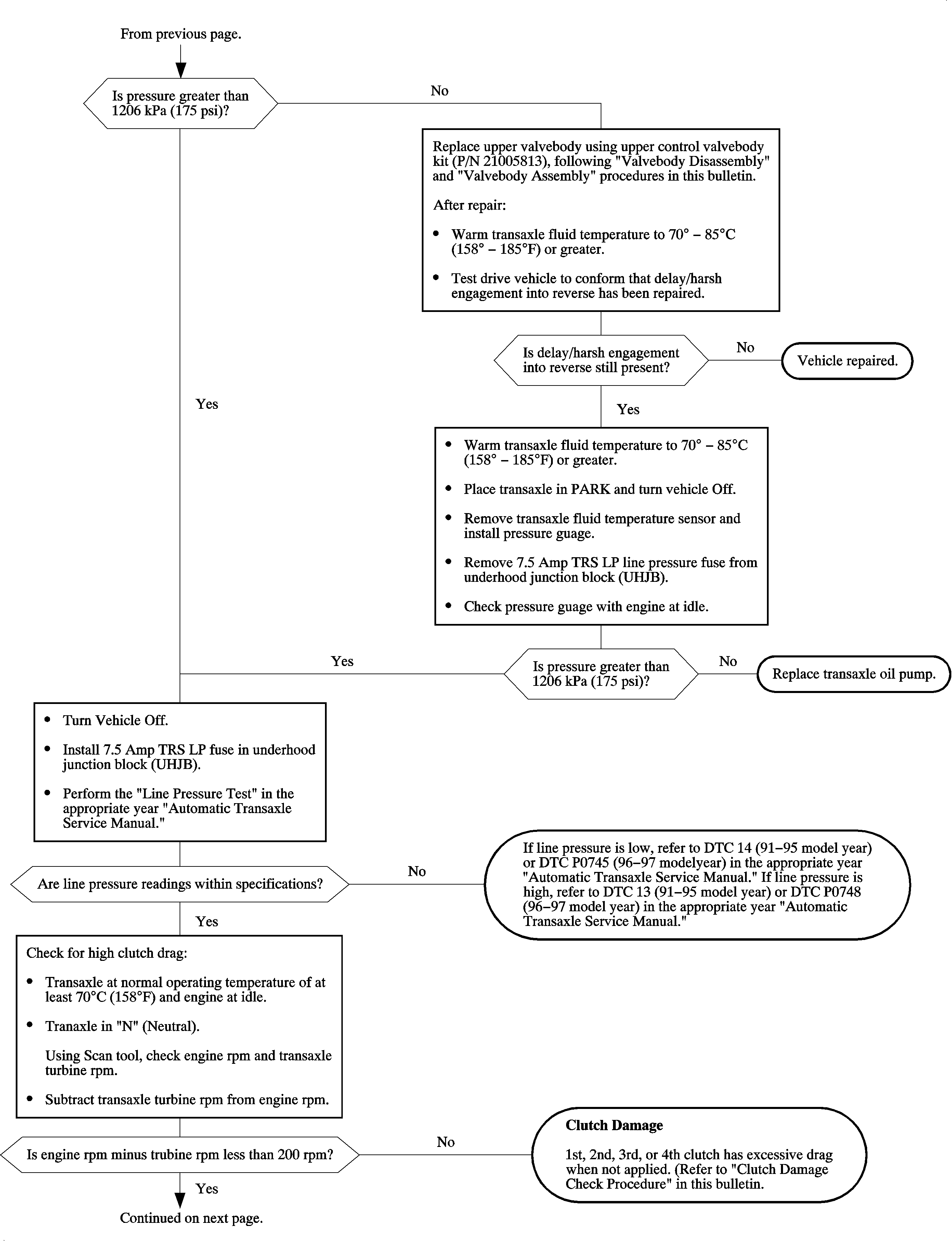
When diagnosing a delay and/or harsh engagement into reverse, refer to the following diagnostic flow chart and procedure. The following diagnostic flow chart and procedure is more thorough than the diagnostic flow chart and procedure contained in the appropriate year Automatic Transxles Service Manuals.
Clutch Damage Check Procedure
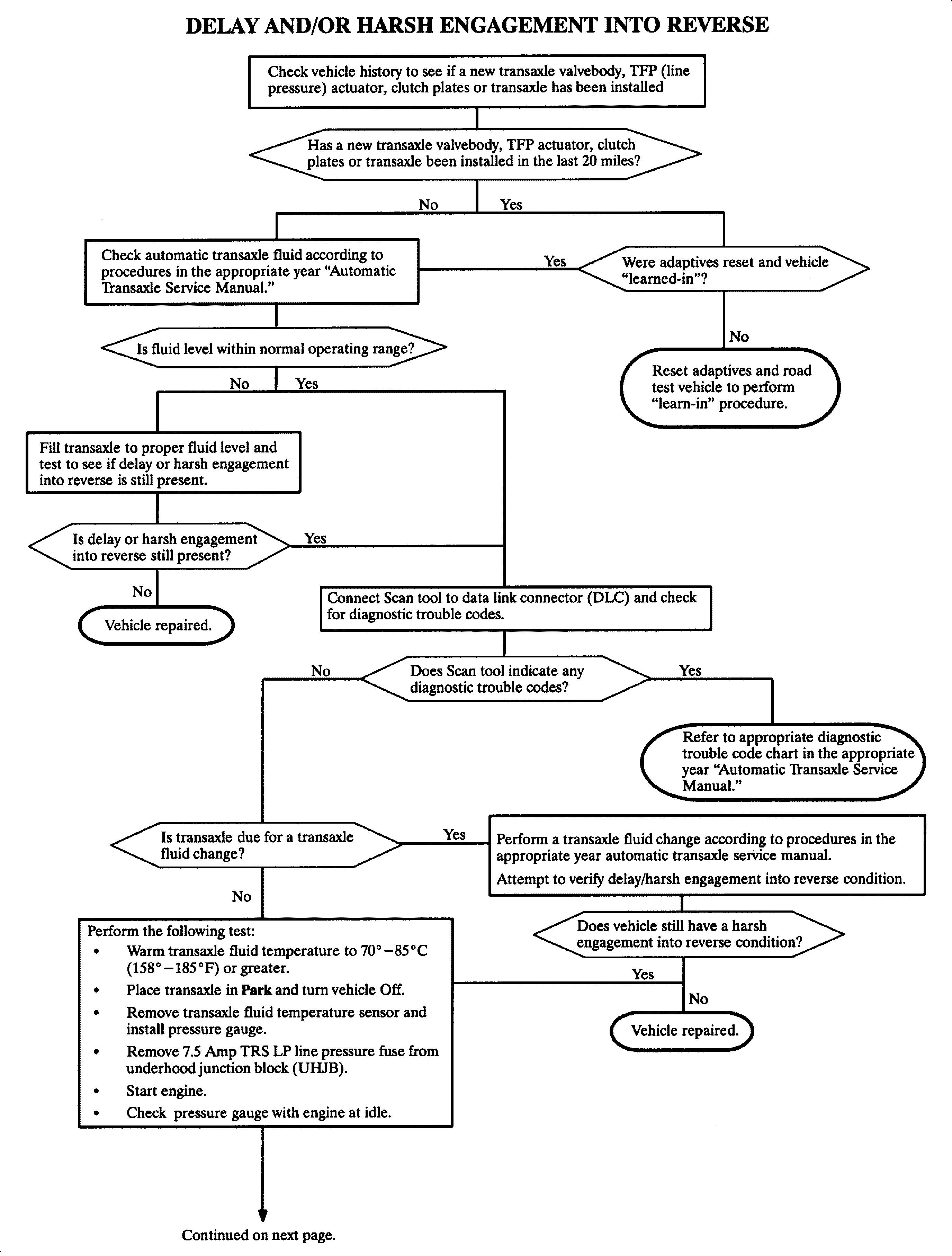
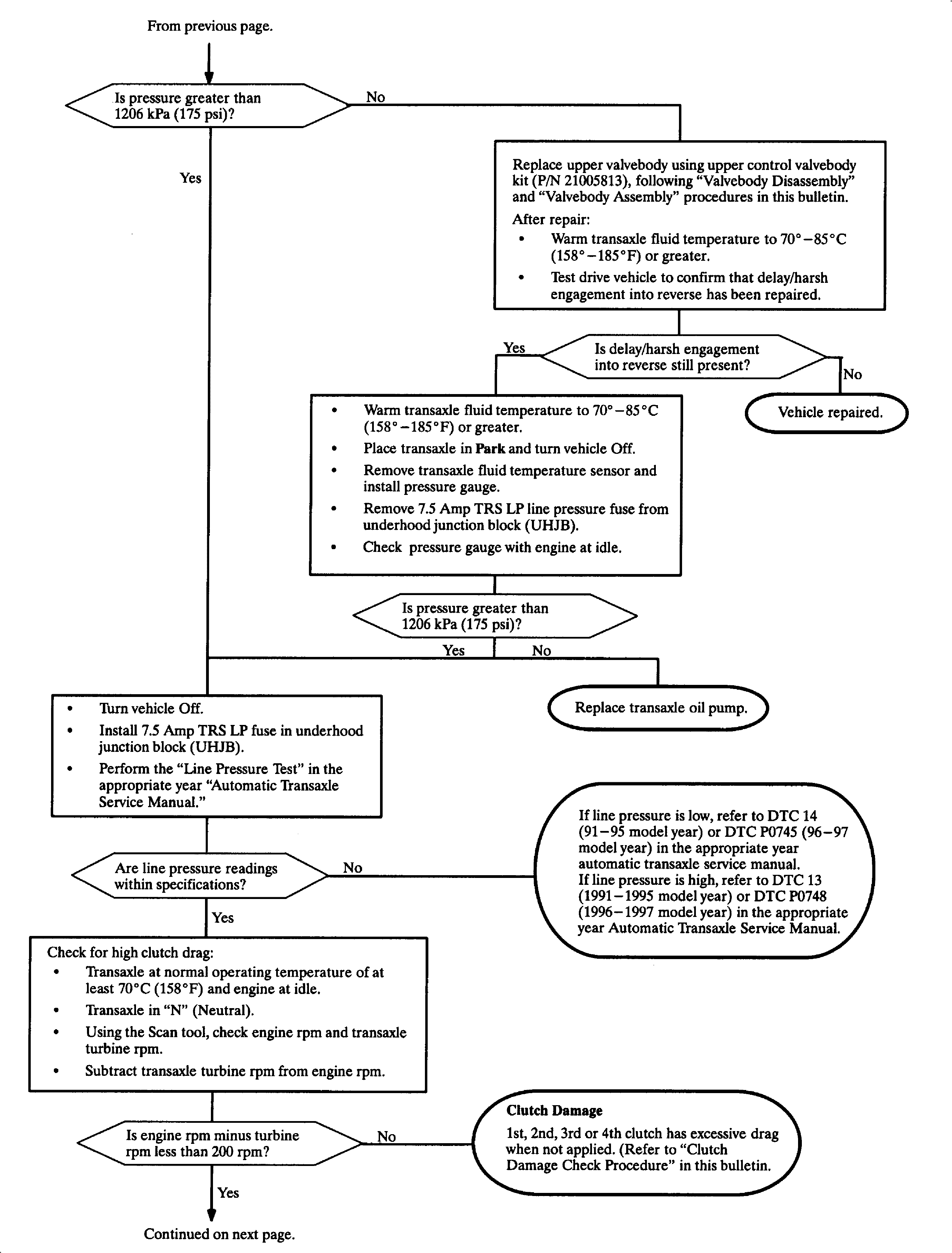
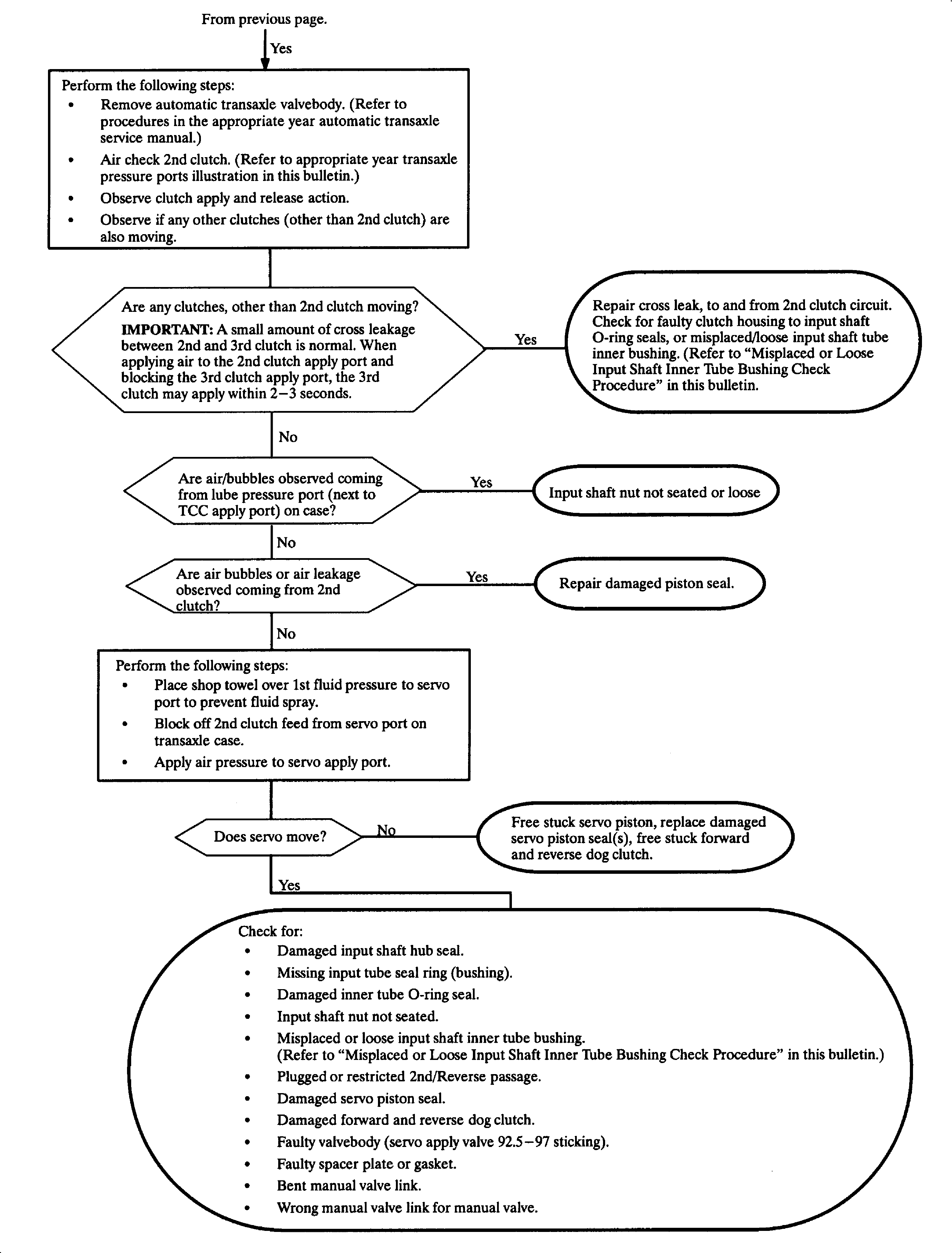
- Place vehicle in Park.
- Remove end cover according to procedures in the appropriate year automatic transaxle service manual.
- Rotate the input shaft by hand, turning the 1st clutch housing in both directions.
| • | If input shaft turns freely in only one direction, the 1st clutch is binding. Repair 1st clutch according to procedures in the appropriate year automatic transaxle service manual. |
| • | If input shaft will not turn freely in either direction, 2nd, 3rd or 4th clutch is binding. Refer to procedures in the appropriate year automatic transaxle service manual. |
Misplaced or Loose Input Shaft Inner Tube Bushing Check Procedure
- Remove end cover and 1st clutch according to procedures in the appropriate year automatic transaxle service manual.
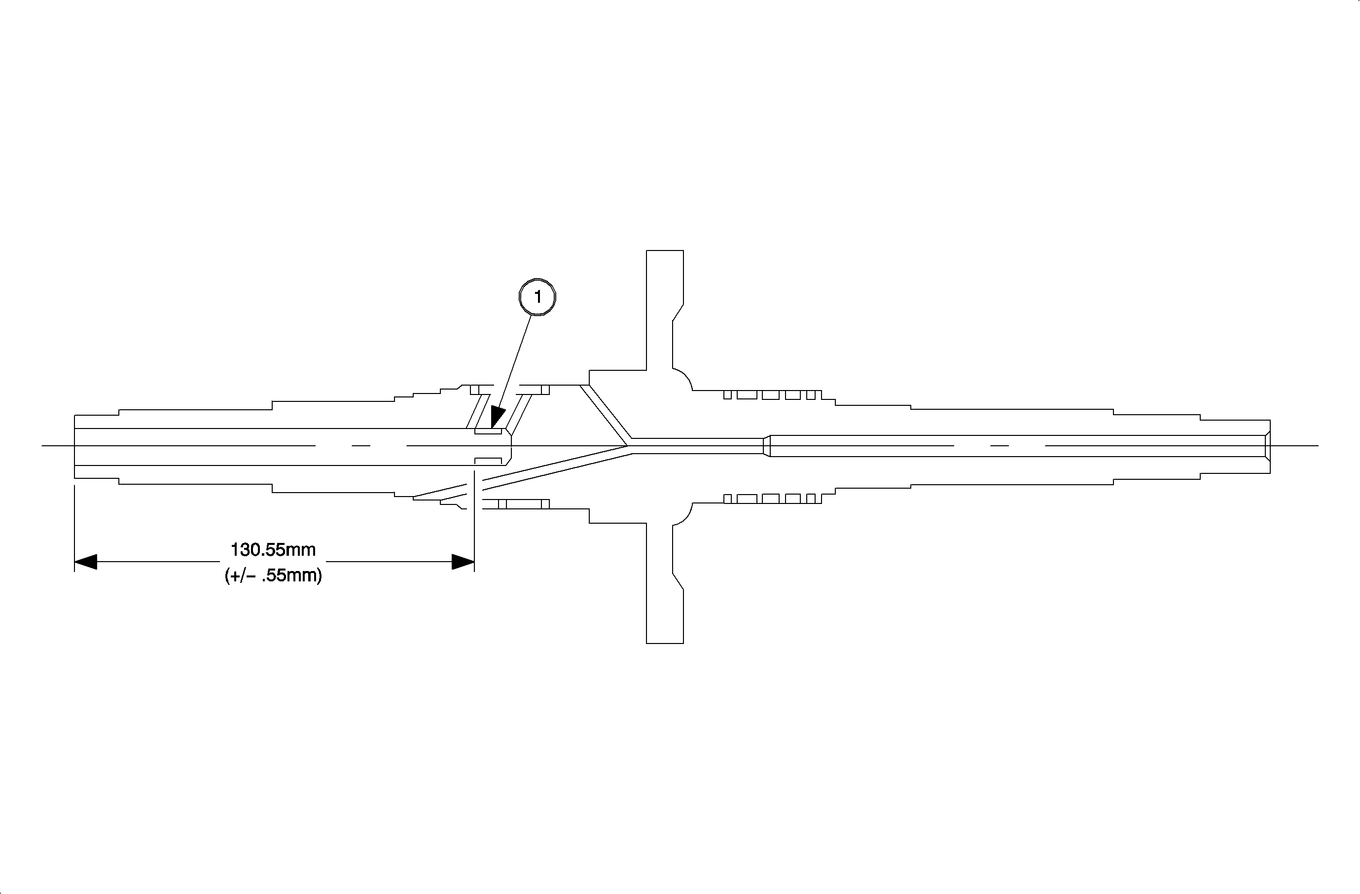
- Obtain a piece of welding rod or straightened coat hanger, and insert into input shaft until the bushing 1 is reached.
- Measure depth of bushing using welding rod or straightened coat hanger and a ruler. The bushing should be 130.18 +/- 3.18 mm (5 1/8 in. +/- 1/8 in.) from the 1st clutch end of the input shaft. If the bushing is more than 133.35 mm (5 1/4 in.) or less than 127.0 mm (5 in.) deep, the input shaft must be replaced.
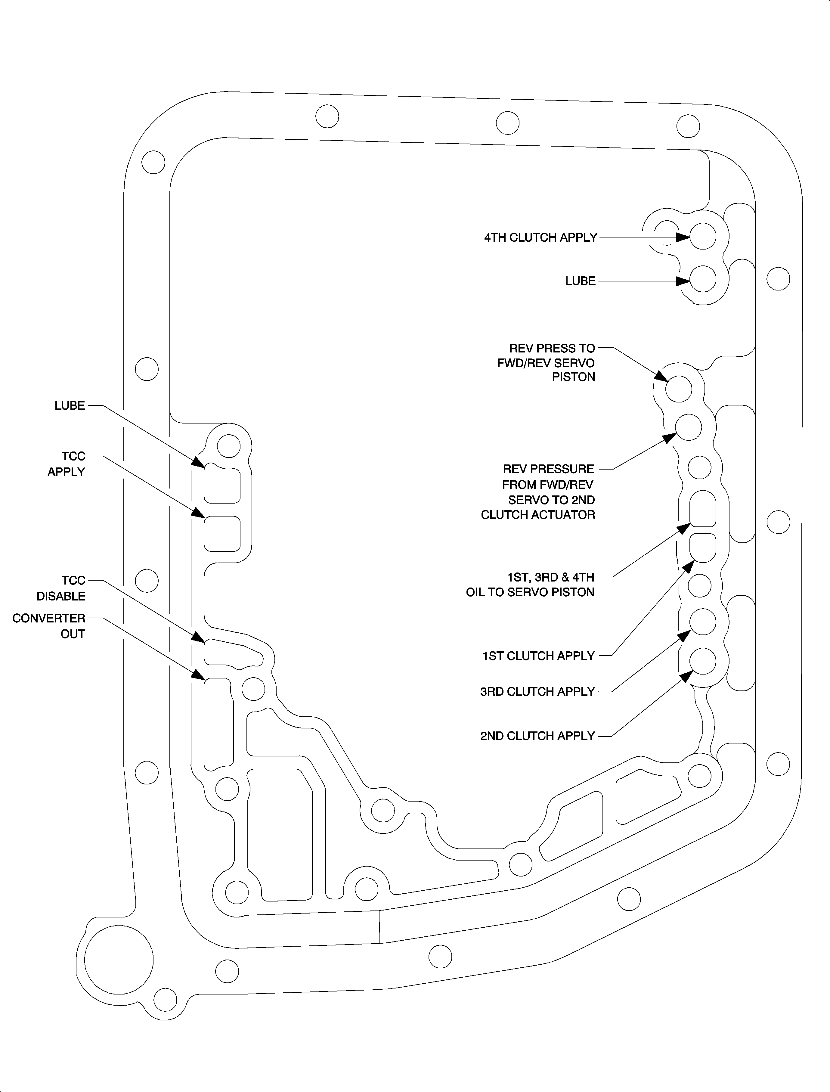
Important: Bolt holes may be different depending on year of vehicle. However, the transaxle case pressure ports are identical from year-to-year:
Procedure
Valvebody Disassembly
- Remove the automatic transaxle control valvebody assembly. (Refer to appropriate year automatic transaxle service manual).
- Remove detent arm.
- Remove actuator cover-to-valvebody bolts (identified by heavy circles) and remove actuator cover.
- Lift actuator connector plate off actuator pins using care not to damage connector plate.
- Remove actuators by using twisting motion as the actuators are removed.
- Remove bolt retaining two halves of valvebody.
- Separate upper valvebody from lower valvebody.
- Remove spacer plate and transaxle check balls.
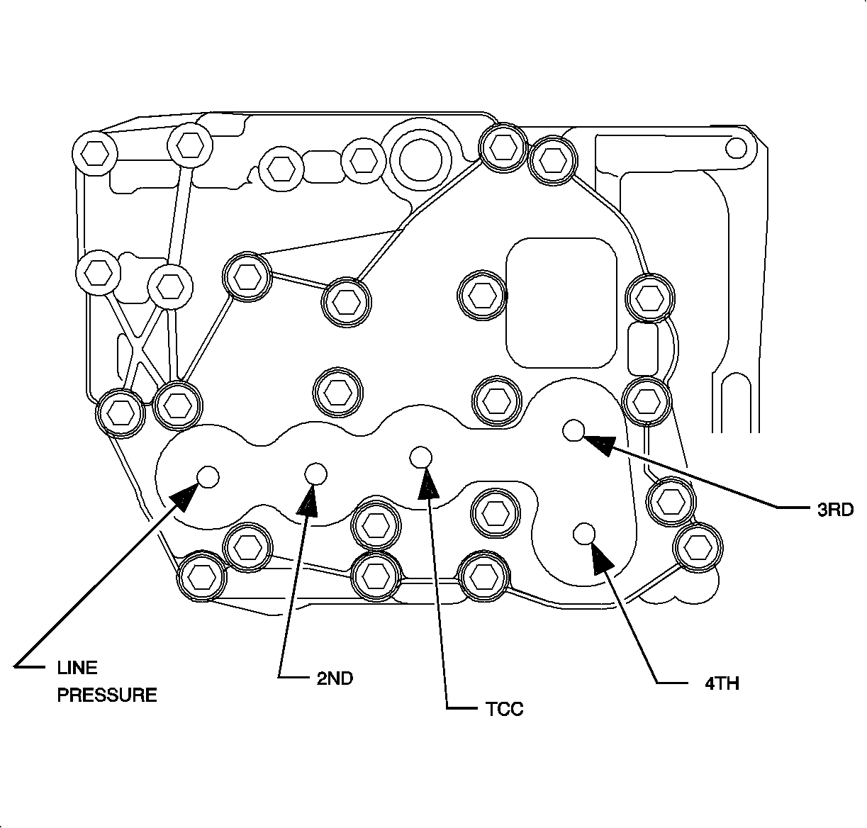
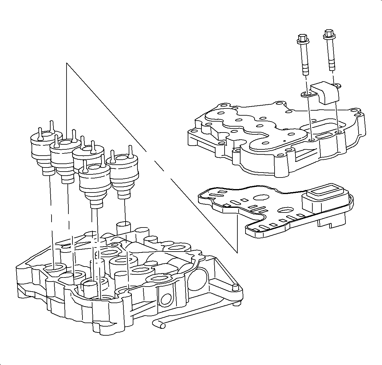
Important: Note position of transaxle check balls when taking two halves apart.
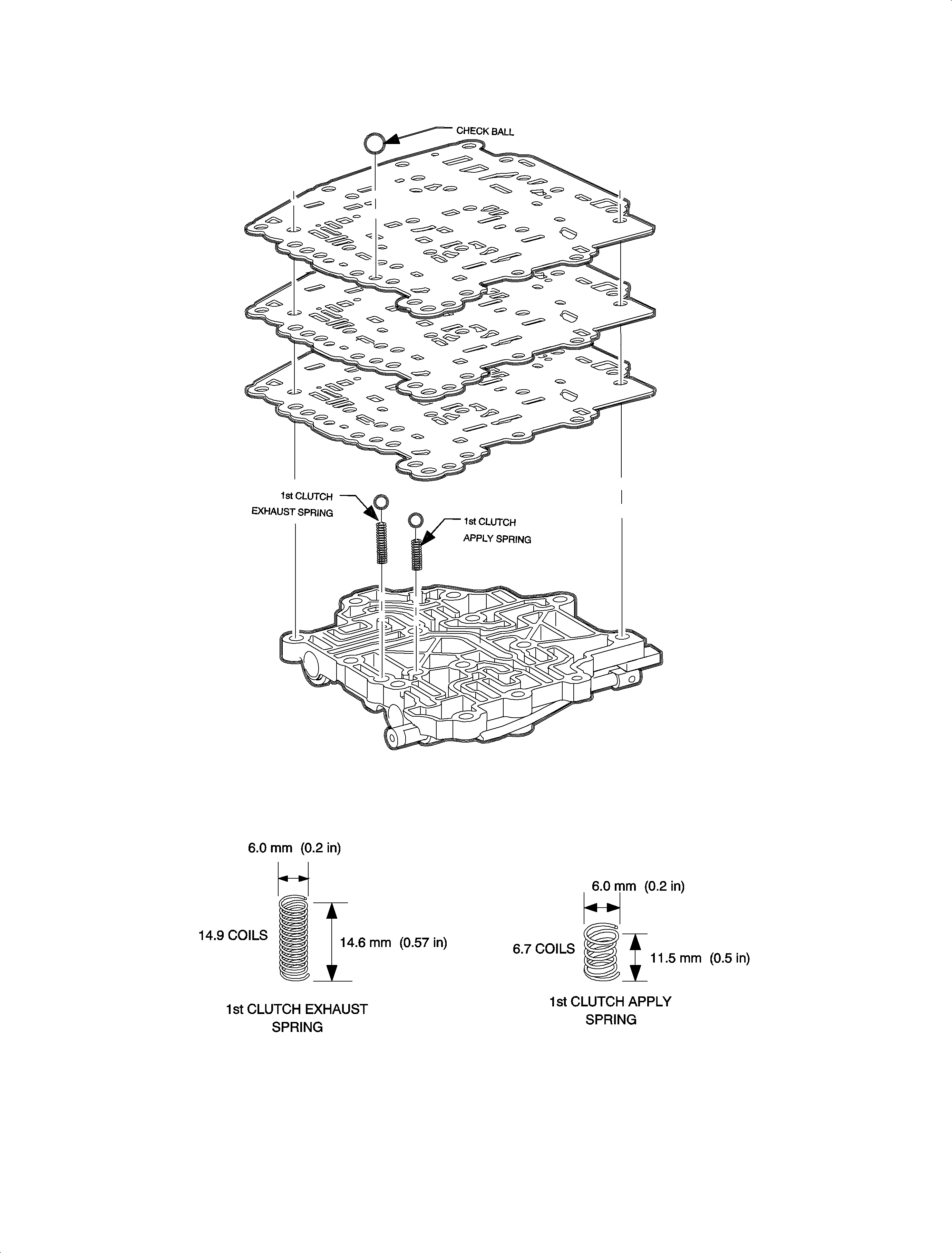
Valvebody Assembly
- Install new spacer plate gaskets on spacer plate.
- Install two transaxle check balls in lower valvebody, on top of springs (refer to illustration on facing page).
- Install new spacer plate on top of lower valvebody and transaxle check balls.
- Install transaxle check ball on top of spacer plate.
- Position new upper control valvebody assembly onto spacer plate (and check balls), and install the one bolt holding the two halves of the valvebody together.
- Lube actuator O-rings.
- Install actuators using a twisting motion.
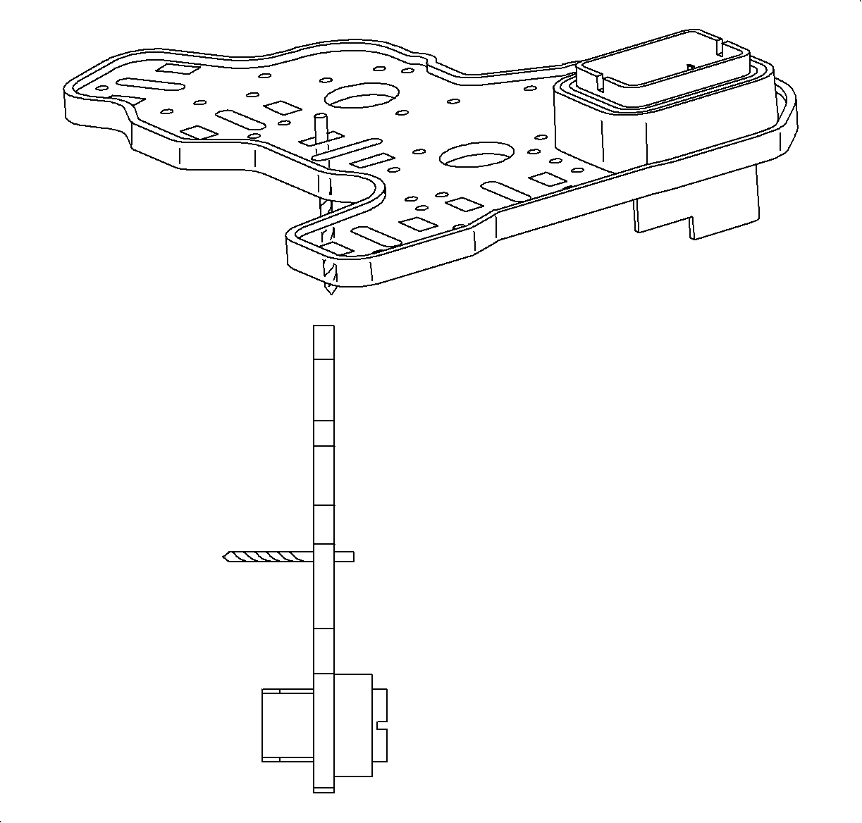
- Check connector plate terminals with a #43 (2.25 mm) drill bit. There should be a slight drag on the shank. If there is no drag, replace the connector plate.
- Align the actuator pins to the connector plate.
- Install the actuator cover.
- Install return exhaust diverter.
- Install the actuator cover bolts and finger tighten.
- Torque actuator cover bolts using torque sequence shown.
- Install detent arm and bolt.
- Install valvebody according to procedures in the appropriate year automatic transaxle service manual.
- If VIN breakpoint is before and including TZ392192, install valvebody cover using Loctite 515 Gasket Eliminator Sealant (P/N 21005993) or equivalent. (Refer to Technical Information Bulletin 95-T-25A [corporation number 587102R] for information on using Loctite 515 Gasket Eliminator Sealant or equivalent for valvebody cover installation.)
Important: Be sure all parts are clean and free of lint and dirt. Valvebody should be assembled in a clean area.
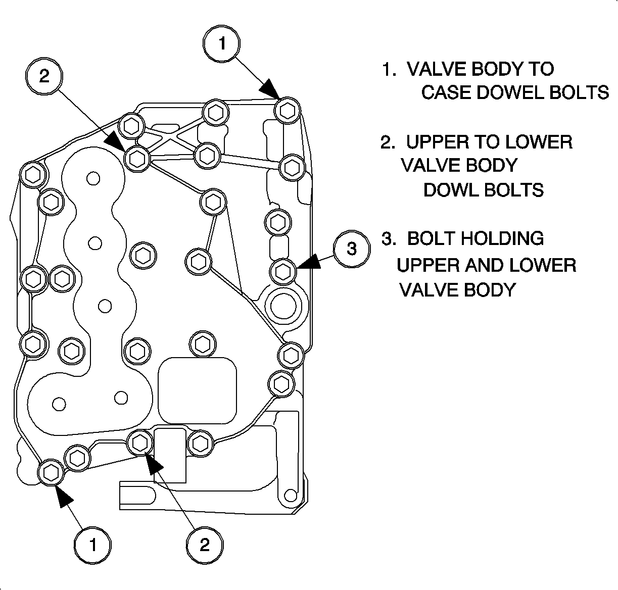
Important: The dowel bolts must be placed in the holes shown to align the upper valvebody to the lower valvebody.
Tighten
Tighten nut to 11 N·m (97 in lbs)
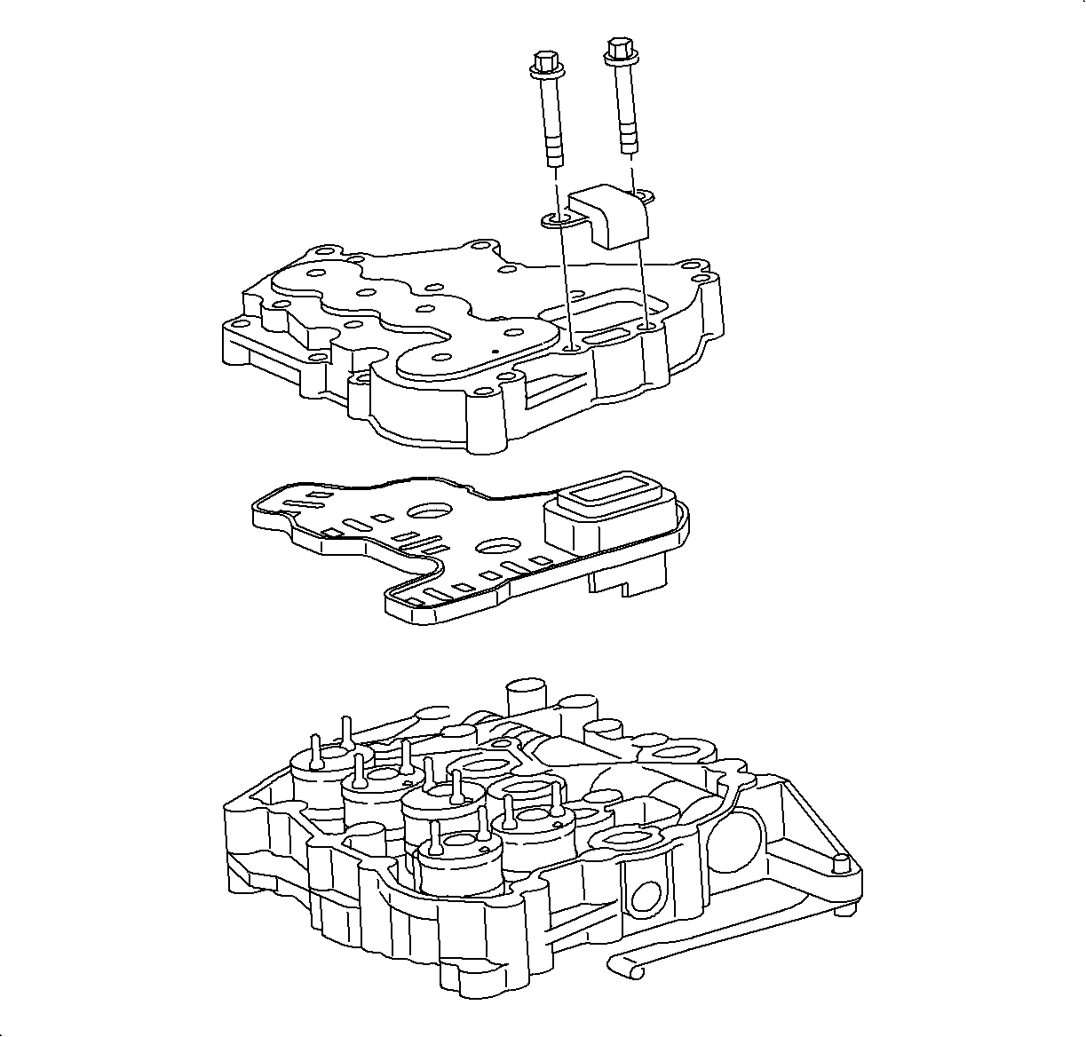

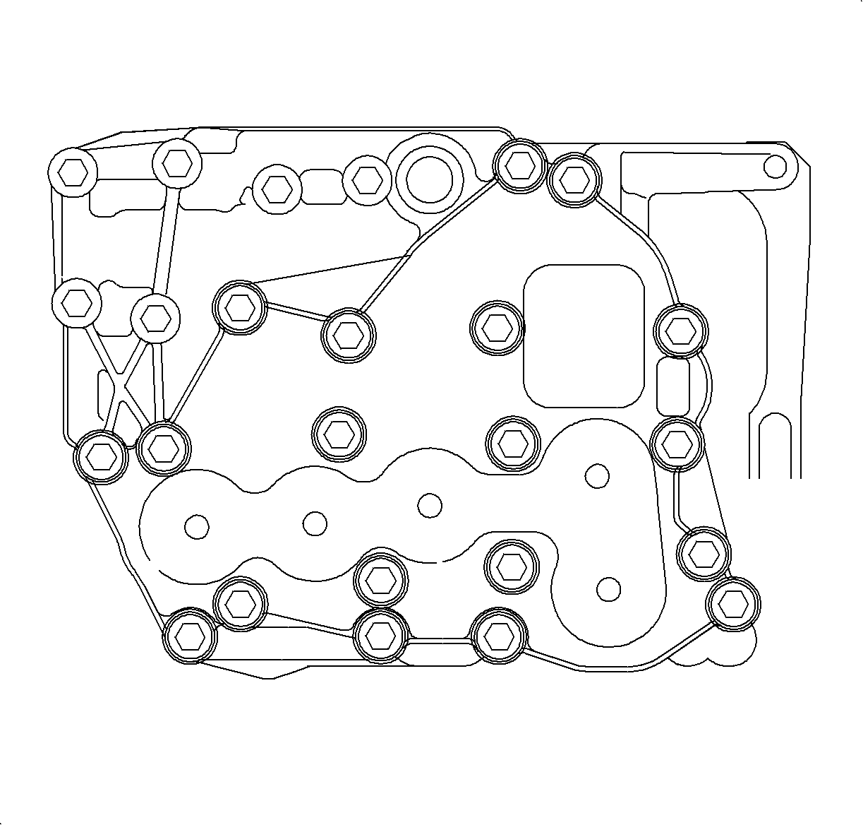
Important: Clean and lubricate all bolts with Saturn Transaxle Fluid. Wipe off excess fluid and install bolts.
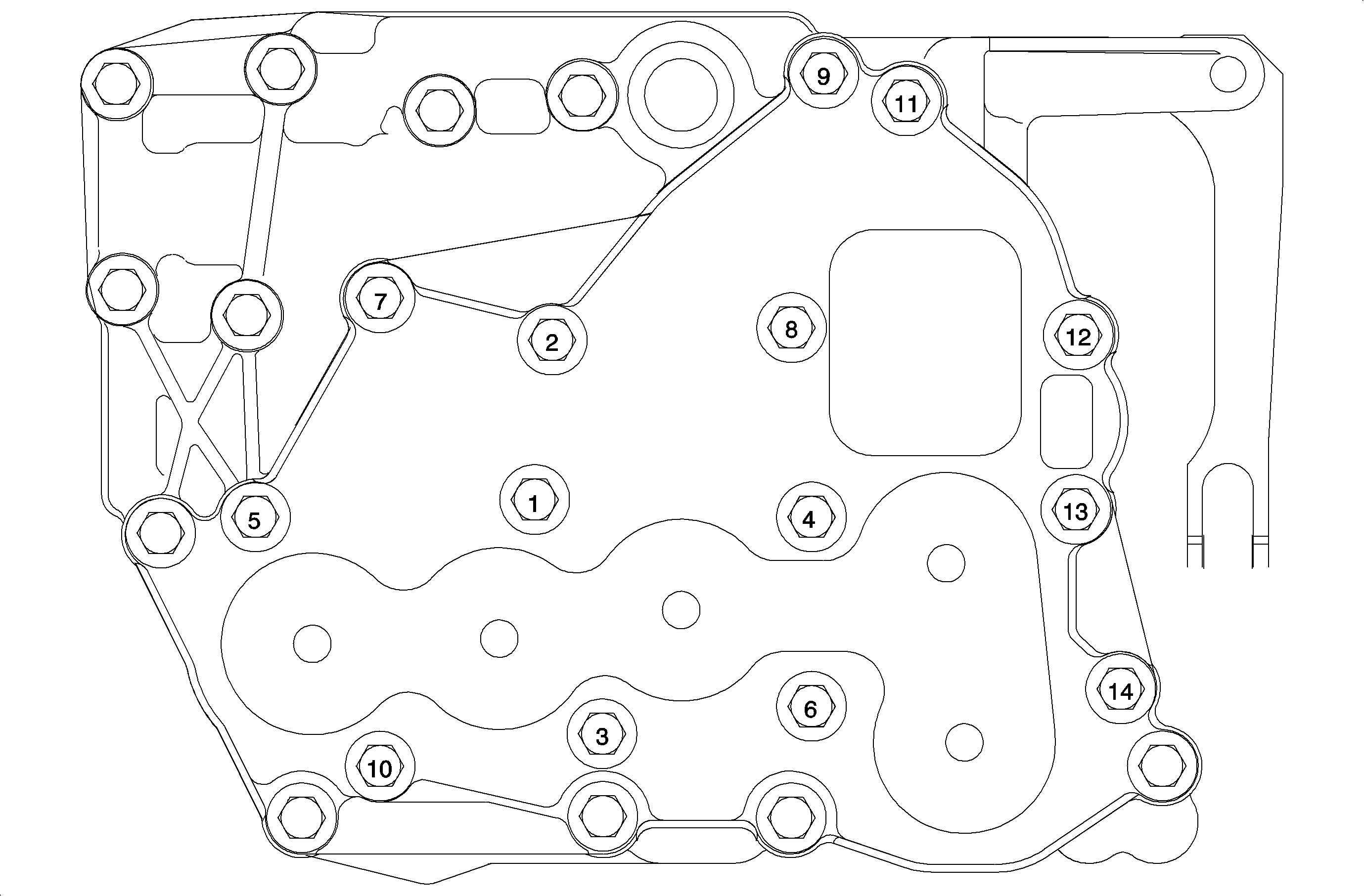
Notice: Over-torquing bolts can cause valves to bind.
Tighten
Tighten nut to 11N·m (97 in lbs)
Tighten
Tighten nut to 11N·m (97 in lbs)
Important: If parts were replaced to repair a line pressure condition, use the Saturn service stall system (SSS) to reset the adaptives before driving vehicle.
Parts Requirements
21005813 | Kit - Upper C/Vlv Body - includes: |
21005944 Assy-Upper C/Vlv Body (Qty1) | |
21003530 Gasket - Spacer Plate (Qty 2) | |
21001683 Gasket -- C/Vlv Body Cvr (Qty 1) | |
21002183 Diverter -- Actr Ret Exh (Qty1) | |
21003529 Plate -- C/Vlv Body Spcr (Qty 1) | |
21003202 Gasket - C/Vlv Body Cvr (Qty 1) | |
21005993 | Sealant - Loctite 515 Gasket Eliminator or equivalent |
Claim Information
To receive credit for repairs using the Upper Control Valve Body Kit during the warranty coverage period, submit a claim through the Saturn Dealer System for K6563 (Replace Upper Control Valvebody Assembly), or if another procedure is performed, refer to the appropriate Electronic Labor Time Guide for the correct Labor Operation Code and Time.
