Mode Control Cable Replacement LHD
Removal Procedure
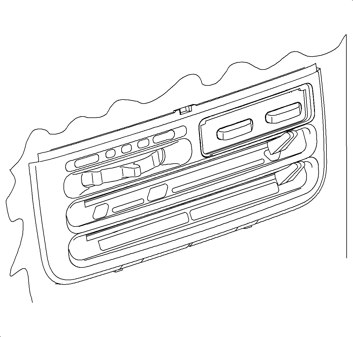
- Depress the center pins inward to release the radio/HVAC controller cover push pin fasteners.
- Remove the fasteners and pull the radio/HVAC controller cover rearward.
- Disconnect the traction control/fog lamp/rear defog electrical connector if equipped.
- Remove the radio screws.
- Push the spring clips in through D-holes on both sides of radio brace.
- Pull the radio out slightly to access the rear of the radio.
- Disconnect the radio electrical connector and antenna.
- Remove the radio.
- Remove the mode cable from HVAC control by the squeezing lock tabs together while pulling the cable housing straight up.
- Remove the cable from the pin by pulling straight up. (Service cable shown in illustration.)
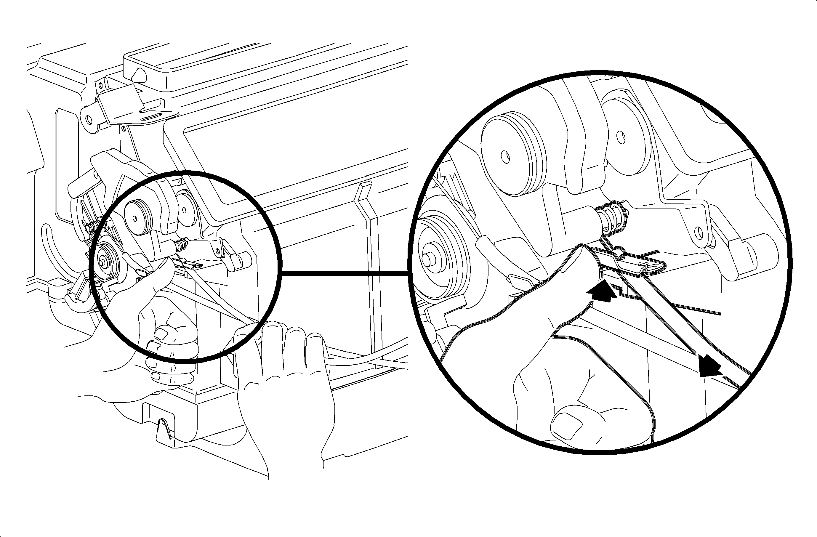
- Reach under the dash and release the mode cable hold down clip by carefully pushing up on the plastic tab while pushing up on the plastic tab while pushing down on top of the cable.
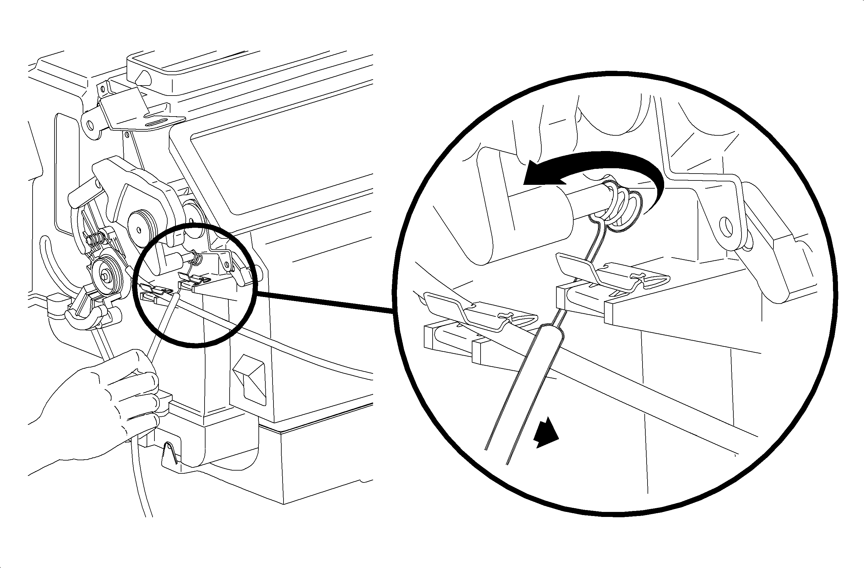
- Rotate the mode valve lever rearward.
- Rotate the cable upward to clear retention leg and slide the cable off the pin.
- Remove the mode cable. (Service linkage shown in illustration.)

Important: Do not push center pins through the fasteners.


Disconnect the blower switch, A/C-Recirc and lighting electrical connectors. Remove the electrical harness clip from the H-bracket.


Installation Procedure
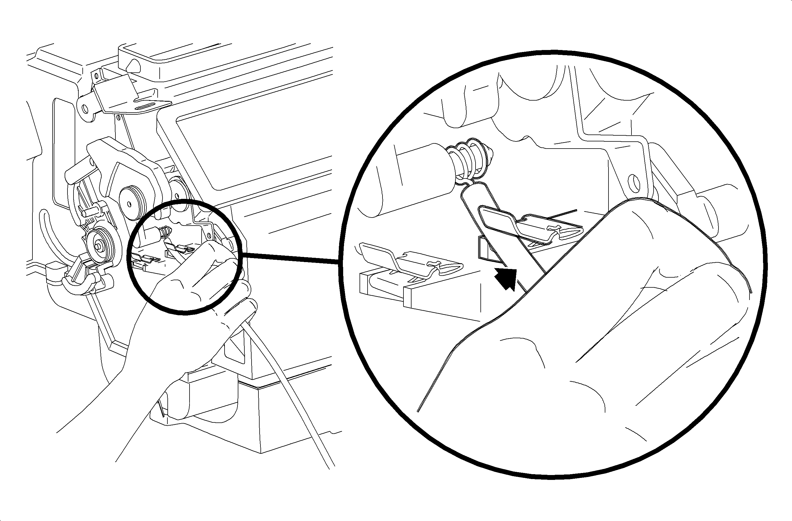
- Install the mode cable over the mode valve pin and behind the retention leg.
- Snap the mode cable hold down clip over the mode cable holder.
- Install the mode cable over the pin.
- Install the mode cable housing into the channel and push down to lock.
- Install the electrical harness clip to module boss.
- Connect the electrical connector and antenna to radio.
- Install the radio.
- Install and tighten the screws.
- Connect the traction control/fog lamp/rear defog electrical connector, if equipped.
- Install the radio/HVAC controller cover. Push in at the clip locations.
- Install the push pins and lock.


Connect the blower switch, A/C-Recirc and lighting electrical connectors.
Important: Make sure the wiring harnesses do not interfere with control lever movement.


Important: Make sure the spring clips are seated in D-holes on both sides.
Tighten
Tighten to 2.5 N·m (22 lbs in)

Mode Control Cable Replacement RHD Domestic Only
Removal Procedure
- Remove the glove box door stops by rotating 90 degrees, and let door hang down.
- Remove screws from glove box compartment and striker.
- Remove glove box assembly by pulling rearward at clip locations.
- Depress the center pins inward to release the radio/HVAC controller cover push pin fasteners.
- Remove the fasteners and pull the radio/HVAC controller cover rearward.
- Disconnect the traction control/fog lamp/rear defog electrical connector if equipped.
- Remove the radio screws.
- Push the spring clips in through D-holes on both sides of radio brace.
- Pull the radio out slightly to access the rear of the radio.
- Disconnect the radio electrical connector and antenna.
- Remove the radio.
- Disconnect the blower switch, A/C-Recirc and lighting electrical connectors. Remove the electrical harness clip from the H-bracket.
- Remove the mode cable from HVAC control by the squeezing lock tabs together while pulling the cable housing straight up.
- Remove the cable from the pin by pulling straight up. (Service cable shown in illustration.)
- Rotate the mode cam fully counterclockwise.
- Remove the mode cable housing from retainer clip by pressing upward on upper tab of clip while gently pulling outward on mode cable housing.
- Remove the mode cable eyelet from mode cam pin by pressing mode cable eyelet towards module case while rotating mode cable outward.
- Remove mode cable.


Important: Do not push center pins through the fasteners.


Installation and Adjustment Procedure.
- Rotate mode cam fully counterclockwise.
- Install mode cable with wire eyelet wrap as shown.
- Install mode cable eyelet between mode cam pin and module case and rotate onto mode cam pin.
- Install mode cable over HVAC control pin.
- Install mode cable housing into channel and push down to lock into place.
- Place HVAC control mode lever completely to the right - defrost position.
- Verify that mode cam is still in full counterclockwise position.
- Press mode cable housing in firmly into retainer clip to lock.
- Move HVAC control mode lever through modes to verify proper installation.
- Install the mode cable over the pin.
- Install the mode cable housing into the channel and push down to lock.
- Connect the blower switch, A/C-Recirc and lighting electrical connectors.
- Connect the electrical connector and antenna to radio.
- Install the radio.
- Install and tighten the screws.
- Connect the traction control/fog lamp/rear defog electrical connector, if equipped.
- Install the radio/HVAC controller cover. Push in at the clip locations.
- Install glove box and snap in at clip locations.
- Install and torque screws.
- Install glove box door stops.
- Adjust striker as necessary.


Important: Do not install mode cable housing into retainer clip at this time.


Important: Make sure the wiring harnesses do not interfere with control lever movement.


Important: Make sure the spring clips are seated in D-holes on both sides.
Tighten
Tighten to 2.5 N·m (22 lbs in)


Tighten
Tighten to 2.2 N·m (20 lbs in)
