For 1990-2009 cars only
Tools Required
| • | SA9203C Axle Clamp Installer |
| • | SA9198C C/V Joint Snap Ring Pliers |
| • | SA9161C Axle Boot Clamp Installer |
Disassembly Procedure
- Remove the wheel drive shaft. Refer to Wheel Drive Shaft Replacement .
- Disconnect the swage ring from the half shaft bar using a hand grinder to cut through the ring, taking care not to damage the half shaft bar.
- Remove large seal retaining clamp. Using a small blade screwdriver release the clamp and discard.
- Separate the boot from the tri-pot housing at the large diameter and slide the boot away from the joint along the axle shaft.
- Wipe the excess grease from the face of the tri-pot spider and the inside of the tri-pot housing.
- Remove the tri-pot housing from the spider and shaft.
- Remove the spider retaining ring from the groove on the axle shaft and slide the spider assembly off of the shaft.
- Remove the boot from the axle shaft.
- Clean the tri-pot joint spider assembly and the housing thoroughly with cleaning solvent.
- Remove all traces of old grease and any contaminants. Dry all the parts.
- Inspect the tri-pot joint components for unusual wear, cracks, and other damage. Replace any needed components.
Notice: Use soft metal or wood in between vice jaws to protect the shaft.


Assembly Procedure
- Install the small swage ring clamp onto the neck of the inner boot. Do not crimp.
- Slide the inner boot onto the shaft and locate the neck of the boot in the proper position in the boot groove on the axle shaft.
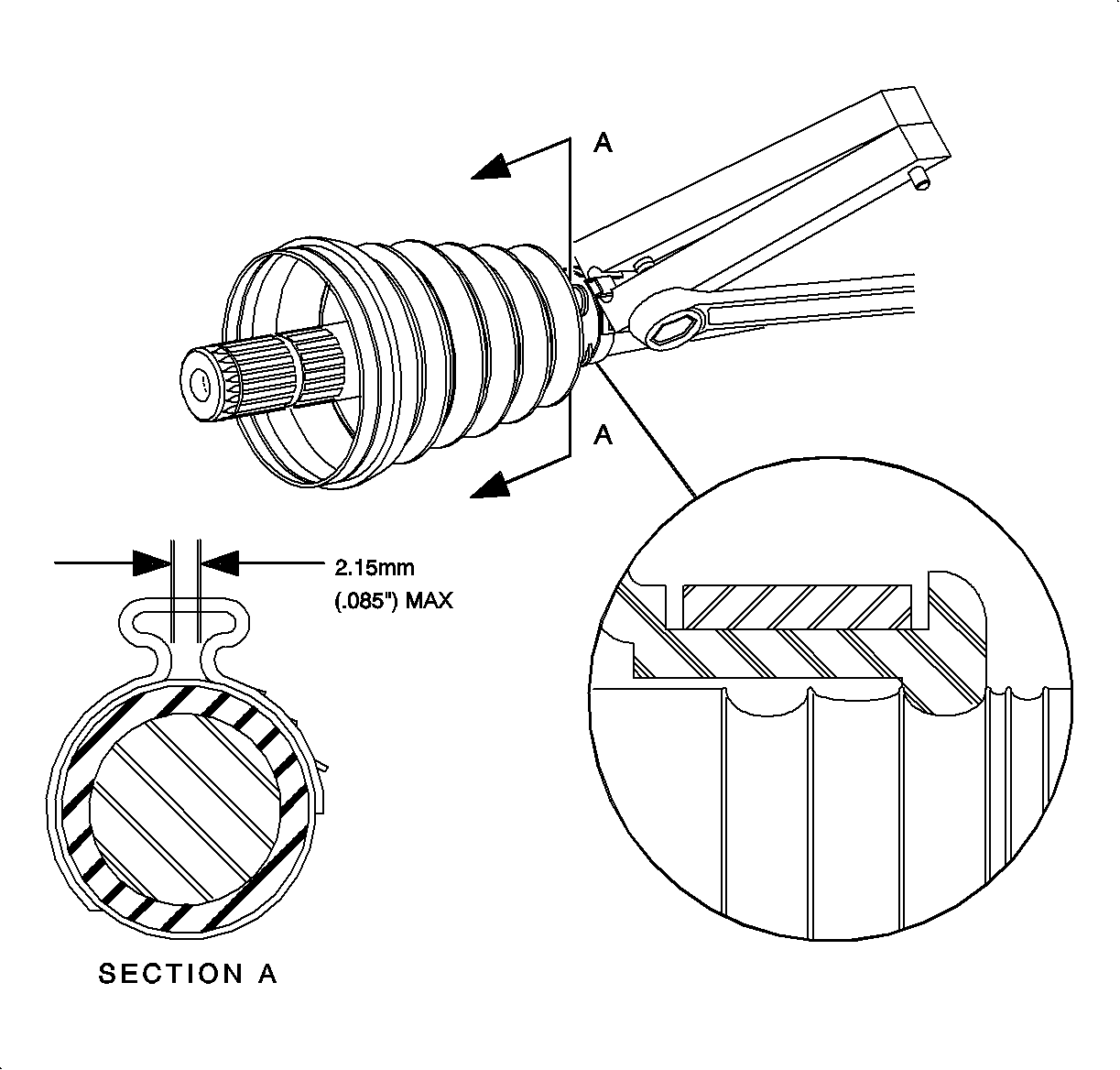
- Swage the boot retaining clamp withSA9203C Axle Boot Clamp Installer, (or equivalent) as shown.
- Measure the clamp end gap, and repeat step 3 if necessary. The dimension should not exceed 2.15 mm (0.85 in).
- Slide the tri-pot spider assembly past the spider retaining ring groove, until seated against shoulder.
- Install the spider retaining ring in the groove of the axle shaft withSA9198C CV Joint Snap Ring Pliers, (or equivalent).
- Place approximately half of the grease (provided in kit) inside boot and use the remainder to repack the tri-pot housing.
- Install the large clamp over the large diameter of the boot.
- Slide the tri-pot housing over the tri-pot spider assembly on the shaft.
- Slide the large diameter of the boot over the outside of the tri-pot housing and position the lip of the boot in the housing groove.
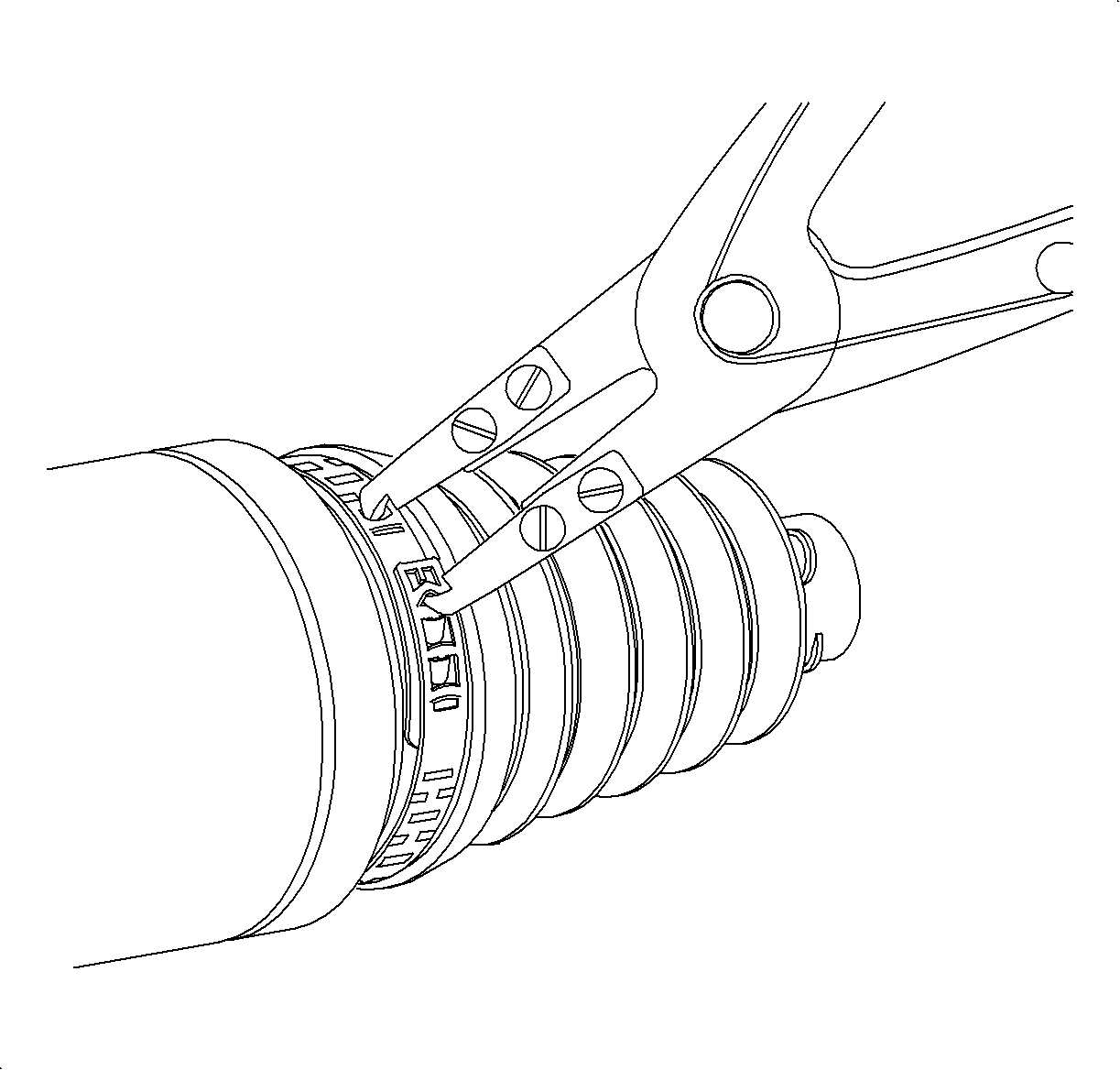
- Place the large boot retaining clamp around the boot and close usingSA9161C Axle Boot Clamp Installer, (or equivalent).
- Install the wheel drive shaft. Refer to Wheel Drive Shaft Replacement .

Important: Check clamp location during swage operation to make sure it is positioned correctly around the entire circumference.


