For 1990-2009 cars only
Removal Procedure
- Select the following HVAC control settings:
- Disconnect the negative battery cable. Refer to Battery Negative Cable Disconnection and Connection in Engine Electrical.
- Remove the thermal expansion valve (TXV). Refer to Thermal Expansion Valve Replacement .
- Remove the instrument panel (I/P) storage compartment. Refer to Instrument Panel Compartment Replacement in Instrument Panel, Gages and Console.
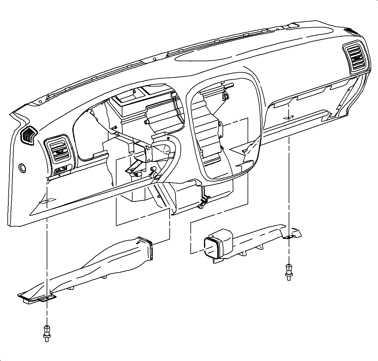
- Remove the right side heater duct assembly retainer.
- Remove the right side heater duct assembly.
- Locate the evaporator access door location on the right side of the module. The entire area inside the raised lip is to be cut out.
- Using a sharp utility knife, cut through the module wall, following inside of the raised bead as a guide. Several passes may be necessary to accomplish this.
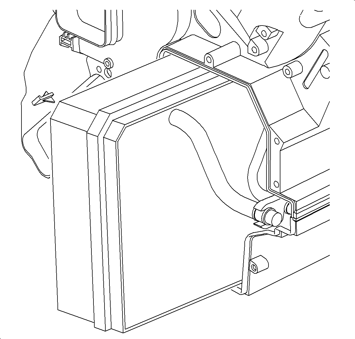
- From the inside of the vehicle, slide the evaporator core out through the access door opening. Use care not to damage the core fins or pipes. Install caps on the pipes to prevent oil spillage.
- Carefully clean out any debris that may be inside of the HVAC module.
| • | Ignition in the ON position |
| • | Recirc to the OFF position |
| • | Ignition in the OFF position |
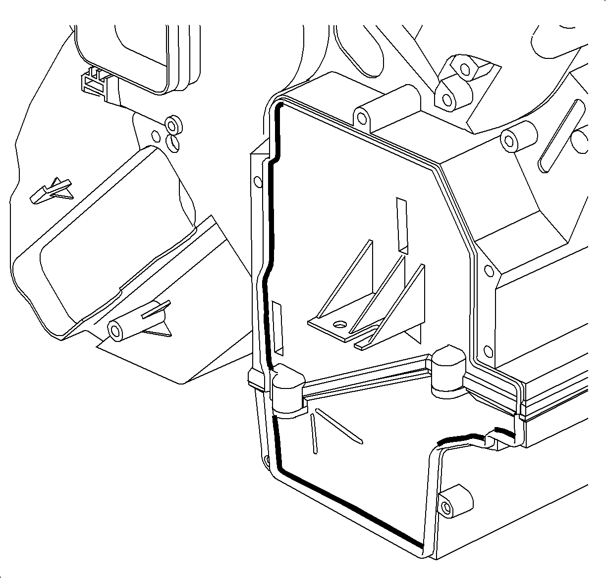
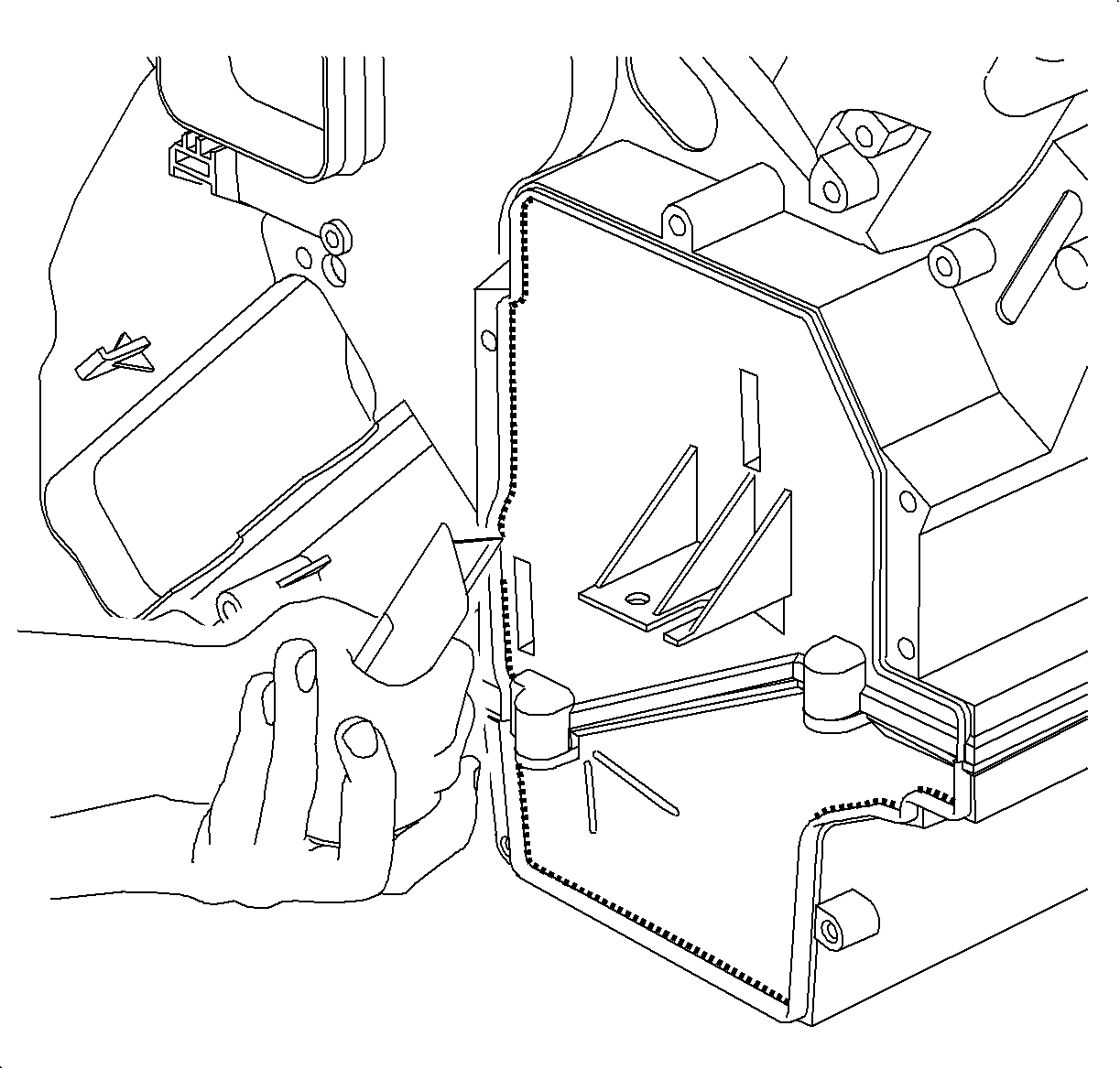
Notice: To avoid cutting internal components, cut only inside raised bead area.
Important: Do not cut through or damage the raised bead, this bead will be used as a sealing surface when completing the procedure.
Installation Procedure
- If replacing the evaporator core, add PAG oil to the evaporator. Refer to Refrigerant System Capacities for system capacity information.
- Lubricate the evaporator O-rings with mineral oil.
- Install the evaporator into the HVAC module.
- Inspect the module to TXV foam seal to verify proper location.
- Install the TXV. Refer to Thermal Expansion Valve Replacement .
- Apply the provided sealant to the service door at the tongue and groove location as shown.
- Install the evaporator core service door to the HVAC module.
- Install the evaporator core service door screws.
- Install the I/P storage compartment. Refer to Instrument Panel Compartment Replacement in Instrument Panel, Gages and Console.
- Install the right side heater outlet duct assembly.
- Install the right side heater outlet duct assembly retainer.
- Connect the negative battery cable. Refer to Battery Negative Cable Disconnection and Connection in Engine Electrical.
- Select the following HVAC control settings:
- Use the back of your hand to inspect for any air leaks around service door.
- Evacuate and recharge the A/C system. Refer to Refrigerant Recovery and Recharging .
- Using the J 39400-A , leak test the fittings of the component.

Use care not to bend the pipes or damage the foam seals.
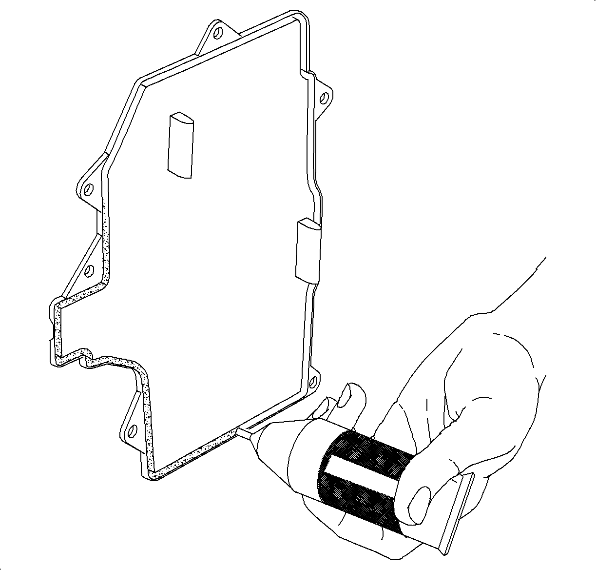
Notice: Proper sealing is important to prevent condensation from leaking into the passenger compartment.
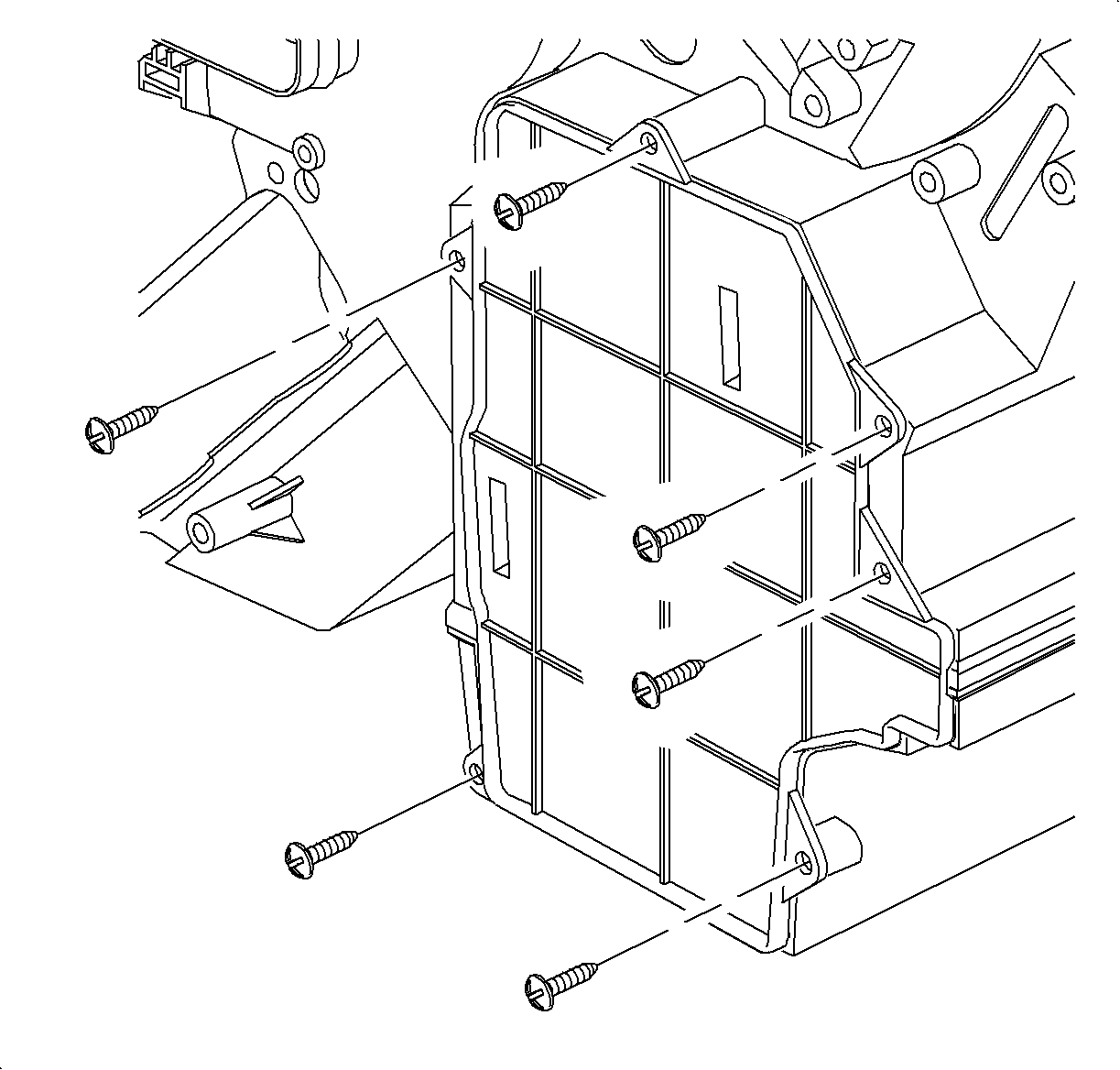
Notice: Refer to Fastener Notice in the Preface section.
Tighten
Tighten the screws to 1.0 N·m (9 lb in).

| • | Highest blower speed |
| • | Mode to the Floor |
| • | Warmest temperature |
| • | Recirc to the OFF position |
If any leaks are found the door must be removed and resealed.
