Removal Procedure
- Remove the intake manifold and spacer. Refer to Intake Manifold Replacement .
- Remove the coolant intake hose.
- Remove the heater hose.
- Remove the coolant bridge bolts.
- Remove the coolant bridge upper seals.
- Remove the coolant bridge.
- Remove the coolant bridge lower seals.
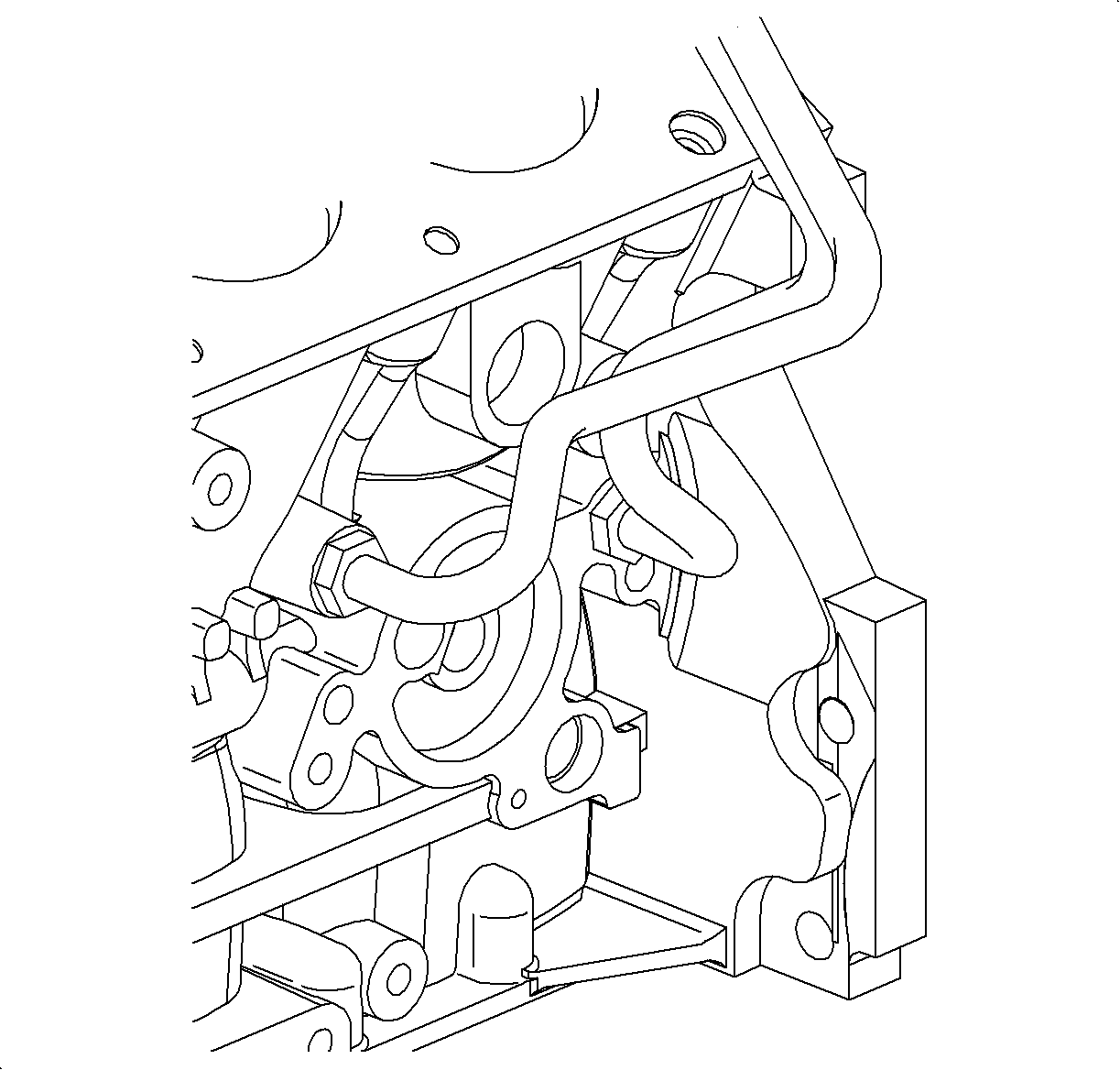
- Remove the oil feed line from the engine oil cooler.
- Remove the return line from the engine oil cooler.
- Take note of the 4 seals.
- Remove the engine oil cooler line clamp.
- Raise and support the vehicle.
- Remove the crank sensor bolt.
- Remove the crank sensor.
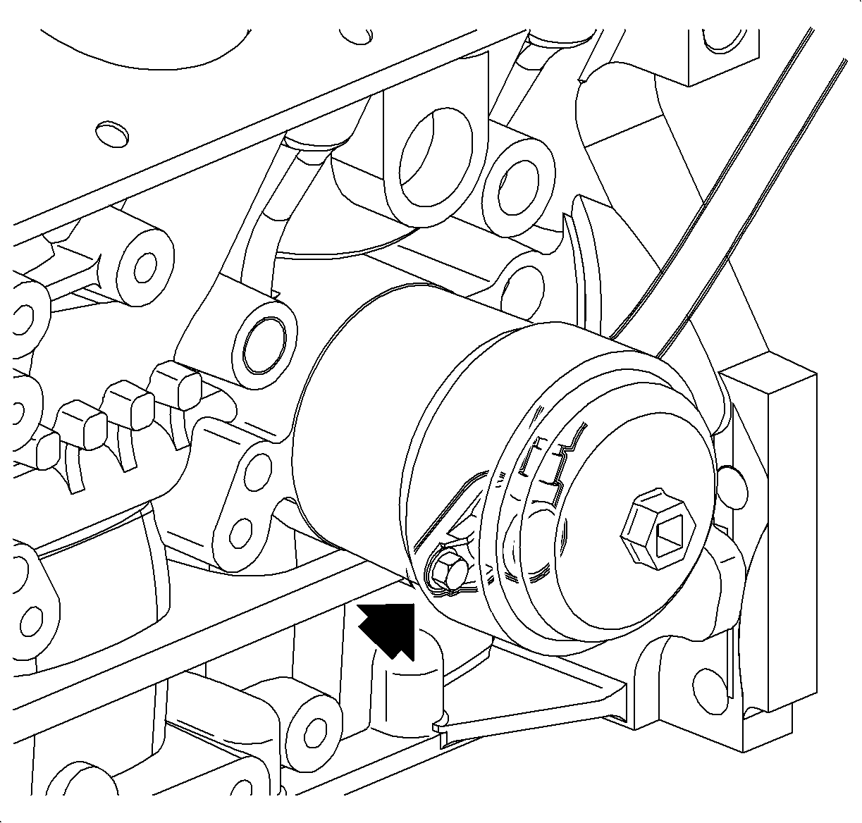
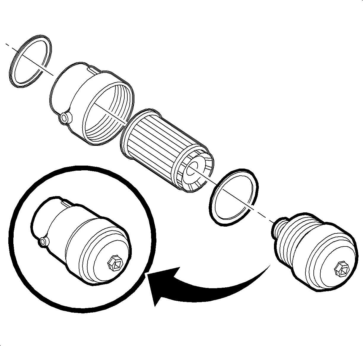
- Remove the oil filter cap and the filter element.
- Remove the oil filter housing.
- Remove the oil feed line from the engine block.
- Remove the return line from the engine block.
- Lower the vehicle.
- Remove the oil feed line.
- Remove the return line.
- Remove the oil feed line from the engine oil cooler.
- Remove the return line from the engine oil cooler.

Caution: Ensure that the vehicle is properly supported and squarely positioned. To help avoid personal injury when a vehicle is on a hoist, provide additional support for the vehicle on the opposite end from which the components are being removed.


Installation Procedure
- Lower the vehicle.
- Install the oil feed and install the return lines to the engine oil cooler. Use 4 new seals.
- Install the engine oil cooler line clamp.
- Raise and support the vehicle.
- Install the oil feed line to the engine block.
- Install the return line to the engine block.
- Install the O-ring onto the oil filter housing.
- Install the oil filter housing onto the engine block and tighten.
- Install the oil filter element, the O-ring, and the oil filter cap onto the housing.
- Install the crank sensor.
- Install the crank sensor bolt.
- Install the coolant bridge and install the coolant bridge lower seals.
- Install the coolant bridge upper seals and the coolant bridge bolts.
- Install the coolant intake housing and install the coolant intake housing O-ring seal.
- Install the coolant intake housing bolts.
- Install the intake manifold and spacer. Refer to Intake Manifold Replacement .
- Check and fill the engine oil as necessary.

Tighten
Tighten the oiler cooler feed and return lines to
engine block to 30 N·m (22 lb ft).

Caution: Ensure that the vehicle is properly supported and squarely positioned. To help avoid personal injury when a vehicle is on a hoist, provide additional support for the vehicle on the opposite end from which the components are being removed.
Tighten
Tighten the oil cooler feed and return lines to
engine block to 30 N·m (22 lb ft).
Tighten
Tighten the oil cooler feed and return lines to
engine block to 30 N·m (22 lb ft).

Tighten
Tighten the oil filter cartridge housing-to-engine
to 45 N·m (33 lb ft).
Tighten
Tighten the oil filter cap to 15 N·m
(11 lb ft).

Tighten
Tighten the crankshaft position sensor bolt to 8 N·m
(71 lb in).

Tighten
Tighten the coolant bridge bolts to 30 N·m
(22 lb ft).

Tighten
Tighten the coolant intake housing bolts to 20 N·m
(15 lb ft).
