For 1990-2009 cars only
Removal Procedure
- Disconnect the negative battery cable. Refer to Battery Negative Cable Disconnection and Connection in Engine Electrical.
- Remove the intake plenum. Refer to Intake Plenum Replacement .
- Remove the intake manifold. Refer to Intake Manifold Replacement .
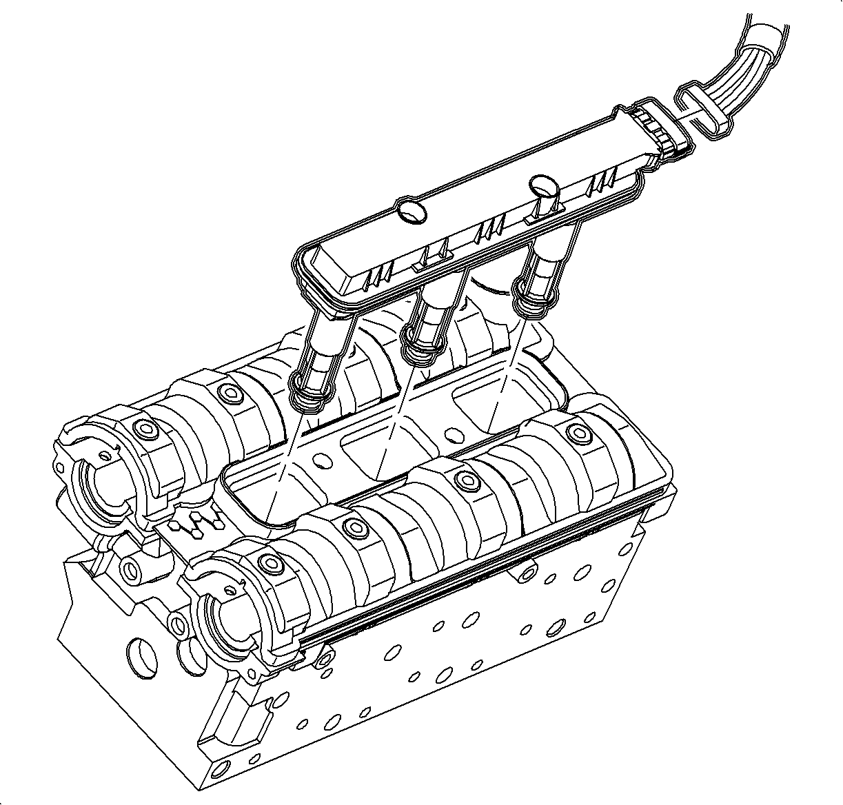
- Remove the ignition module.
- Remove the knock sensor wire harness.
- Remove the lift bracket.
- Remove the camshaft cover bolts.
- Remove the camshaft cover.
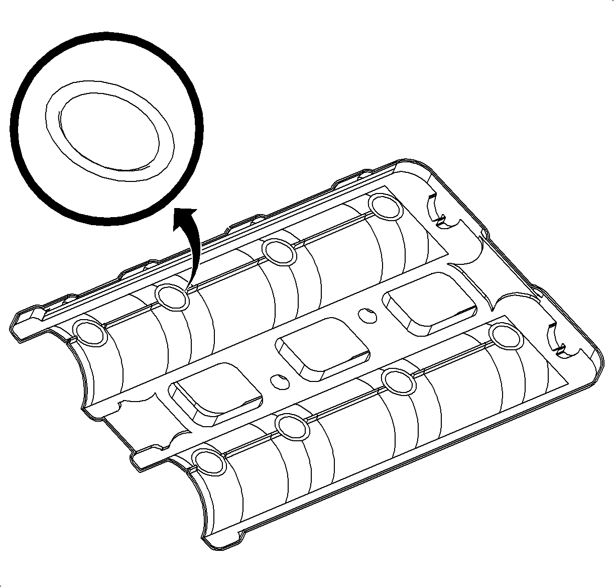
- Remove the camshaft cover seals.
- Clean the camshaft cover.
- Clean all of the sealing surfaces.


Important: Ensure all 8 sealing O-rings are accounted for. The O-rings may stick to the camshaft bearing caps or they may fall into the oil pan.
Installation Procedure
- Lightly coat the new seals, including the O-rings, with engine oil prior to installation to assist in holding the O-ring seals to the valve cover.
- Install the camshaft cover seals.
- Apply a thin coat of LOCTITE® 5900 or equivalent at the front and back of the camshaft cover as shown in the figure as the shaded areas.
- Install the camshaft cover to the cylinder head.
- Install the camshaft cover bolts.
- Install the lift bracket.
- Install the ignition module.
- Install the intake manifold. Refer to Intake Manifold Replacement .
- Install the intake plenum. Refer to Intake Plenum Replacement .
- Connect the negative battery cable.
- Start the engine and inspect for oil leaks.


Notice: Refer to Fastener Notice in the Preface section.
Tighten
Tighten the camshaft cover bolts to 8 N·m
(71 lb in).
Tighten
Tighten the engine lift bracket bolts to 8 N·m
(71 lb in).

Tighten
Tighten the ignition module bolts to 8 N·m
(71 lb in).
Tighten
Tighten the battery terminal bolts to 17 N·m
(13 lb ft).
