Tools Required
| • | J 35268-A Camshaft/Front Main Seal Installer |
| • | J 42069 Timing Belt Alignment Kit |
Removal Procedure
- Disconnect the negative battery cable. Refer to Battery Negative Cable Disconnection and Connection in Engine Electrical.
- Remove the intake plenum. Refer to Intake Plenum Replacement .
- Remove the air cleaner assembly.
- Remove the rear camshaft cover. Refer to Camshaft Cover Replacement .
- Remove the timing belt cover. Refer to Timing Belt Rear Cover Replacement .
- Remove the timing belt. Refer to Timing Belt Replacement .
- Insert the J 42069-2 Camshaft Locking Tool into the camshaft gears to hold the gear in place while loosening the camshaft gear bolt.
- Remove the J 42069-2.
- Remove the camshaft gear bolt.
- Remove the camshaft gear.
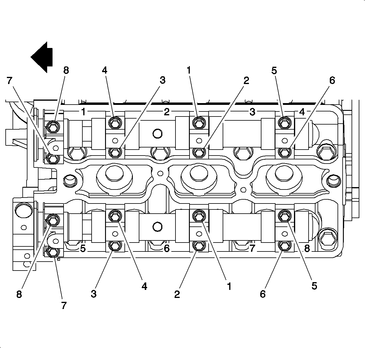
- Loosen the camshaft bearing cap bolts sequentially, starting from the center and moving outwards in a spiral direction in stages of 1/2-1 turn.
- Remove the camshaft bearing cap bolts.
- Remove the camshaft bearing caps. Note the code marks on the bearing caps.
- Remove the camshaft with the seal attached.
- Remove the camshaft seal.
- Clean all of the bearing surfaces.
- Clean all of the sealing surfaces.
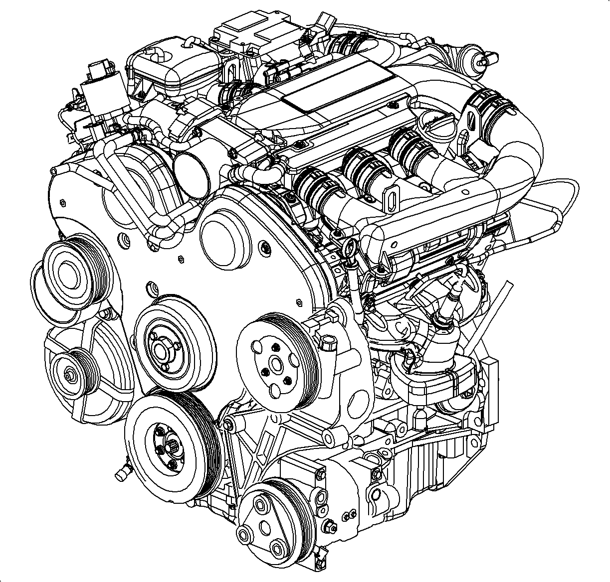
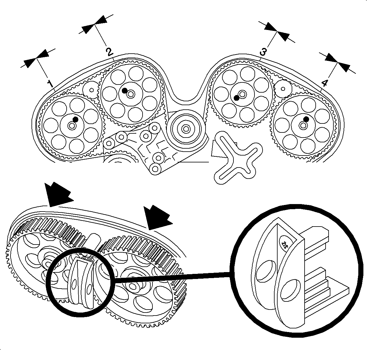
Important: As a precaution, rotate the crankshaft counterclockwise to 60 degrees before top dead center (BTDC) position to prevent valve/piston contact.
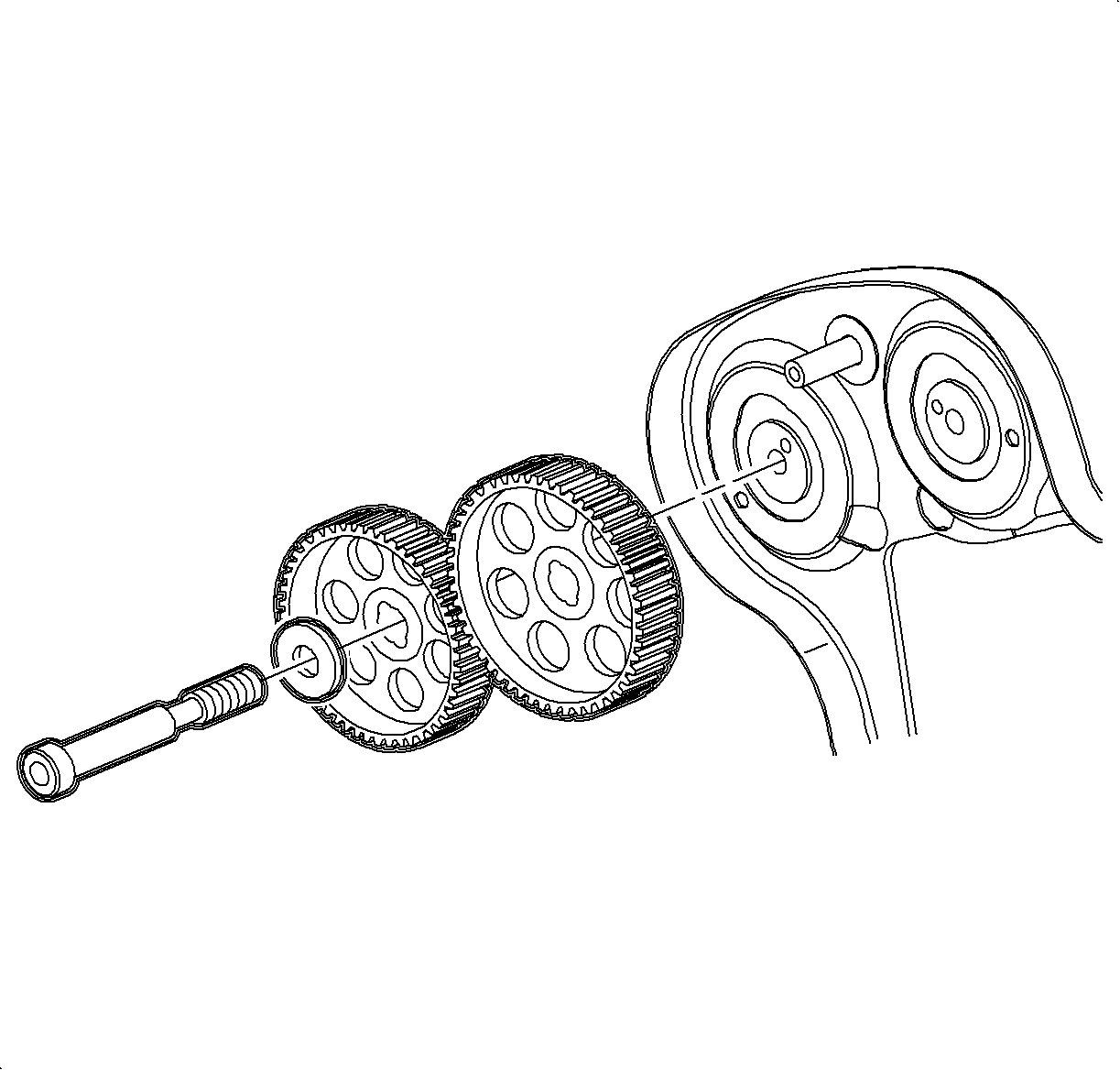

Important: Ensure that the camshaft is not under load from the lifters and that the camshaft comes out of the bearing seats evenly.
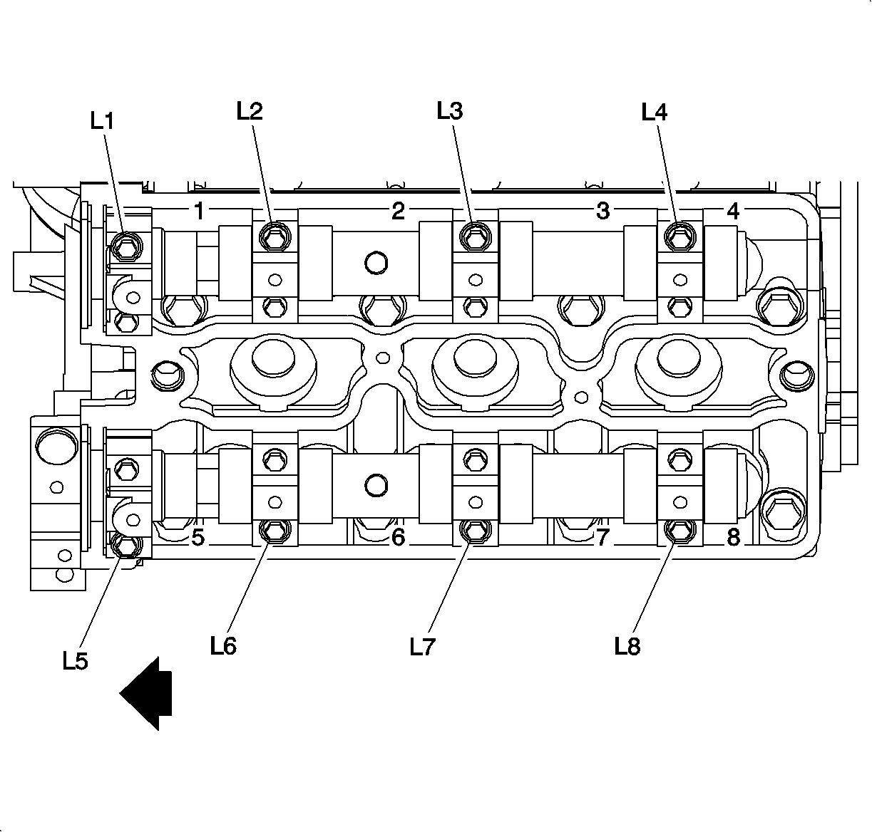
Important: The bearing caps for the rear side (CYL 1, 3, 5) cylinder head are marked with an L followed by a number.
Installation Procedure
- Lubricate the camshaft bearing surfaces with clean engine oil.
- Install the camshaft to the cylinder head.
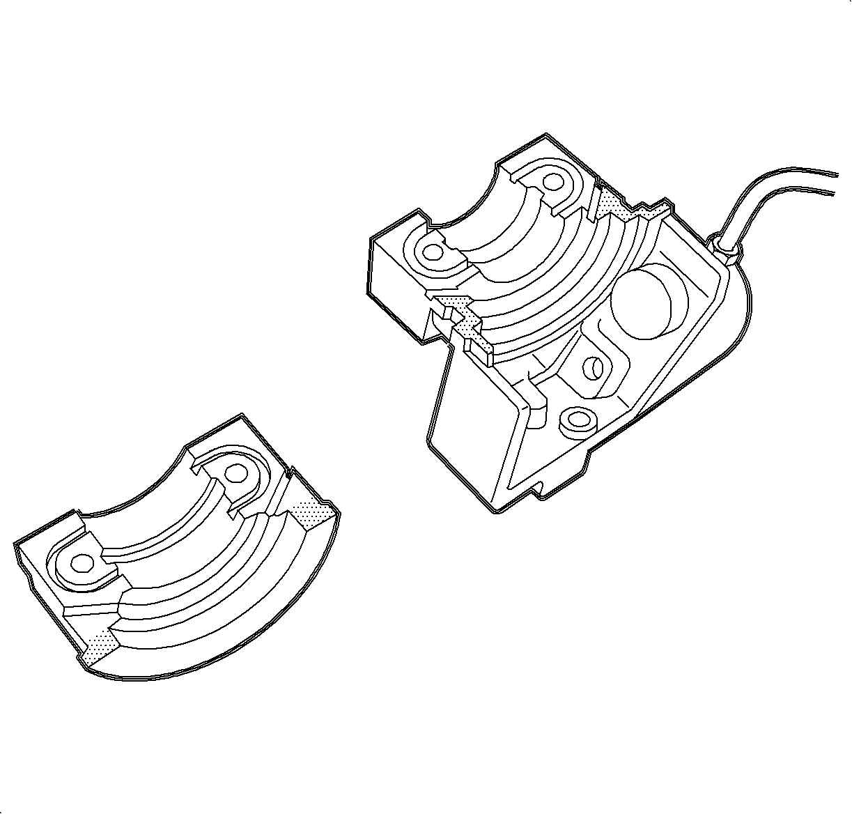
- Apply a small amount of LOCTITE® 518, or equivalent, on the forward edge of the front bearing caps to ensure an adequate seal between the bearing cap and the cylinder head.
- The bearing caps for rear (CYL 1, 3, 5) cylinder head are marked L1-L8 (cylinder 1, 3, 5).
- Install the camshaft bearing caps in their appropriate position.
- Install the camshaft bearing cap bolts.
- Coat the lip of the seal with a small amount of clean engine oil to aid in the installation.
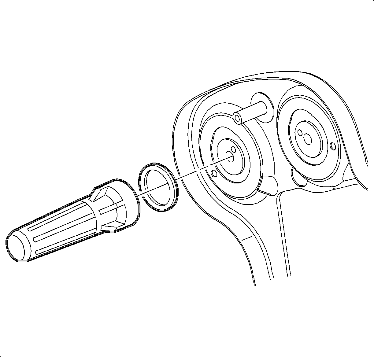
- Use the J 35268-A to tap the camshaft seal into place.
- Ensure that the camshaft seal is fully and evenly seated.
- Install the camshaft gear bolt. Use the J 42069 and J 42069-2 camshaft gear locks to lock the camshaft gears while tightening.
- Install the timing belt. Refer to Timing Belt Replacement .
- Adjust the timing belt. Refer to Timing Belt Replacement .
- Install the timing belt cover. Refer to Timing Belt Rear Cover Replacement .
- Install the front camshaft cover. Refer to Camshaft Cover Replacement .
- Install the intake plenum. Refer to Intake Plenum Replacement .
- Install the air cleaner assembly.
- Connect the negative battery cable.
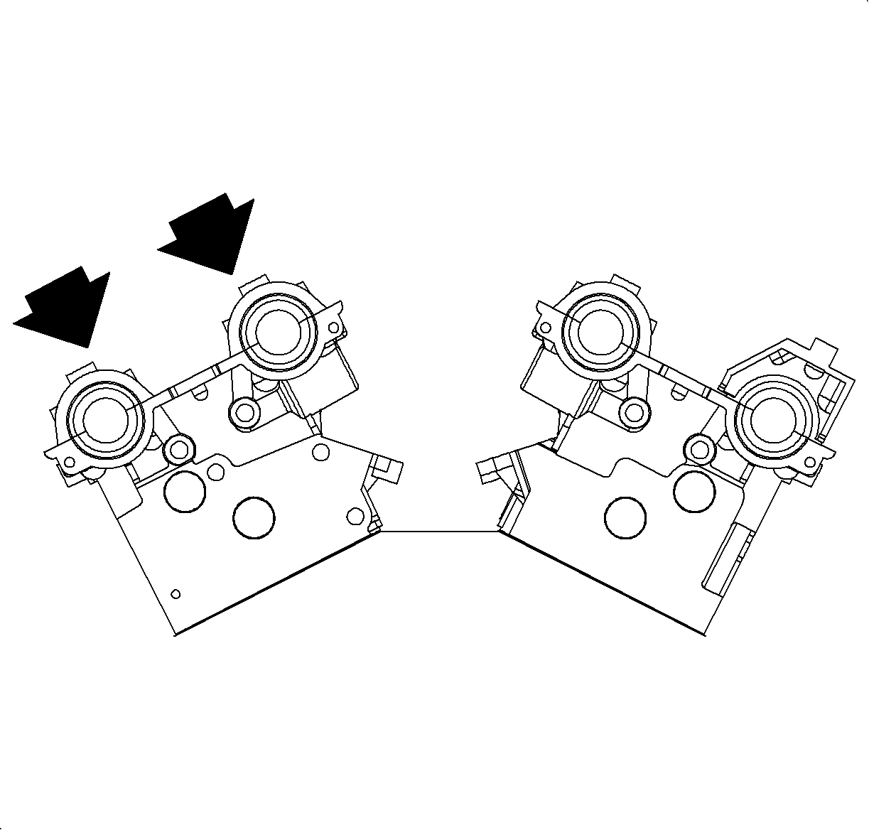
Important: The intake camshaft is marked with the letter A and the exhaust camshaft is marked with the letter E.
Important: Ensure the pin on the exhaust camshaft is approximately in the 1 o'clock position and/or that the pin on the intake camshaft is approximately in the 11 o'clock position to allow for minimal load on the camshaft when installing the bearing caps.
Notice: Refer to Fastener Notice in the Preface section.
Important: Do not allow the sealer to get into the oil journal of the cap.
Tighten
Tighten the camshaft bearing cap bolts to 8 N·m
(71 lb in).

Important: Use a new camshaft gear bolt. The required tightening method will stretch the bolt to its yield point. Therefore, the bolt is not reusable.
Tighten
Tighten the camshaft gear bolt to 50 N·m
(37 lb ft) plus 60 degrees plus 15 degrees.
Tighten
Tighten the battery terminal bolts to 17 N·m
(13 lb ft).
