Cylinder Head Replacement Front
Tools Required
SA9140E Torque Angle Gage
Removal Procedure
- Disconnect the negative battery cable. Refer to Battery Negative Cable Disconnection and Connection in Engine Electrical.
- Remove the intake air cleaner. Refer to Air Cleaner Assembly Replacement .
- Remove the intake plenum. Refer to Intake Plenum Replacement .
- Remove the intake manifold. Refer to Intake Manifold Replacement .
- Remove the intake manifold spacer bolts.
- Remove the intake manifold spacer.
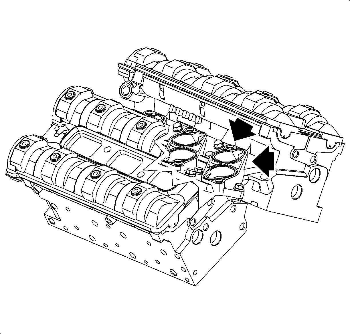
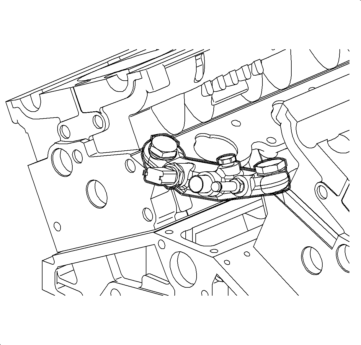
- Remove the coolant bridge.
- Drain the coolant.
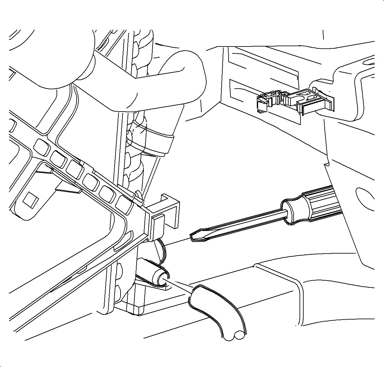
- Remove the upper radiator hose from the coolant extension housing.
- Support the powertrain using a floor jack under the oil pan.
- Remove the front transaxle mount through the bolt.
- Raise the powertrain with a floor jack in order to provide clearance to pull out the extension housing over the coolant module.
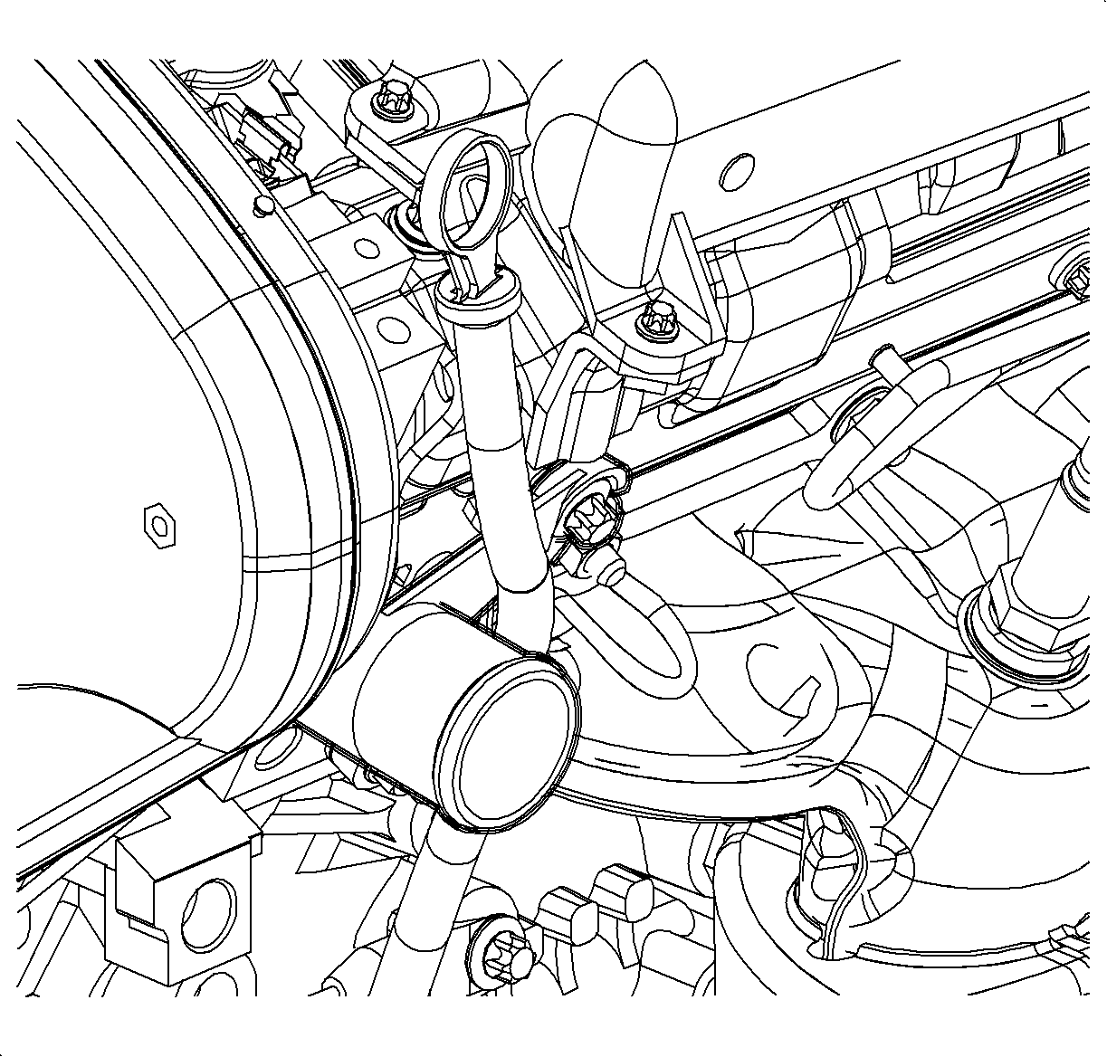
- Remove the oil level indicator tube and coolant extension tube bolt.
- Remove the oil level indicator tube by pulling upwards.
- Twist the coolant extension housing to remove.
- Remove the front camshaft cover. Refer to Camshaft Cover Replacement .
- Remove the grounds from the front lift bracket.
- Disconnect the oxygen sensor electrical connection.
- Remove the down pipe to the exhaust manifold nuts.
- Remove the front timing belt cover. Refer to Timing Belt Front Cover Replacement .
- Remove the timing belt. Refer to Timing Belt Replacement .
- Remove the timing belt tensioner bracket. Refer to Timing Belt Replacement .
- Remove the rear timing belt cover. Refer to Timing Belt Front Cover Replacement .
- Remove the camshaft sensor electrical connection.
- Remove the exhaust camshaft.
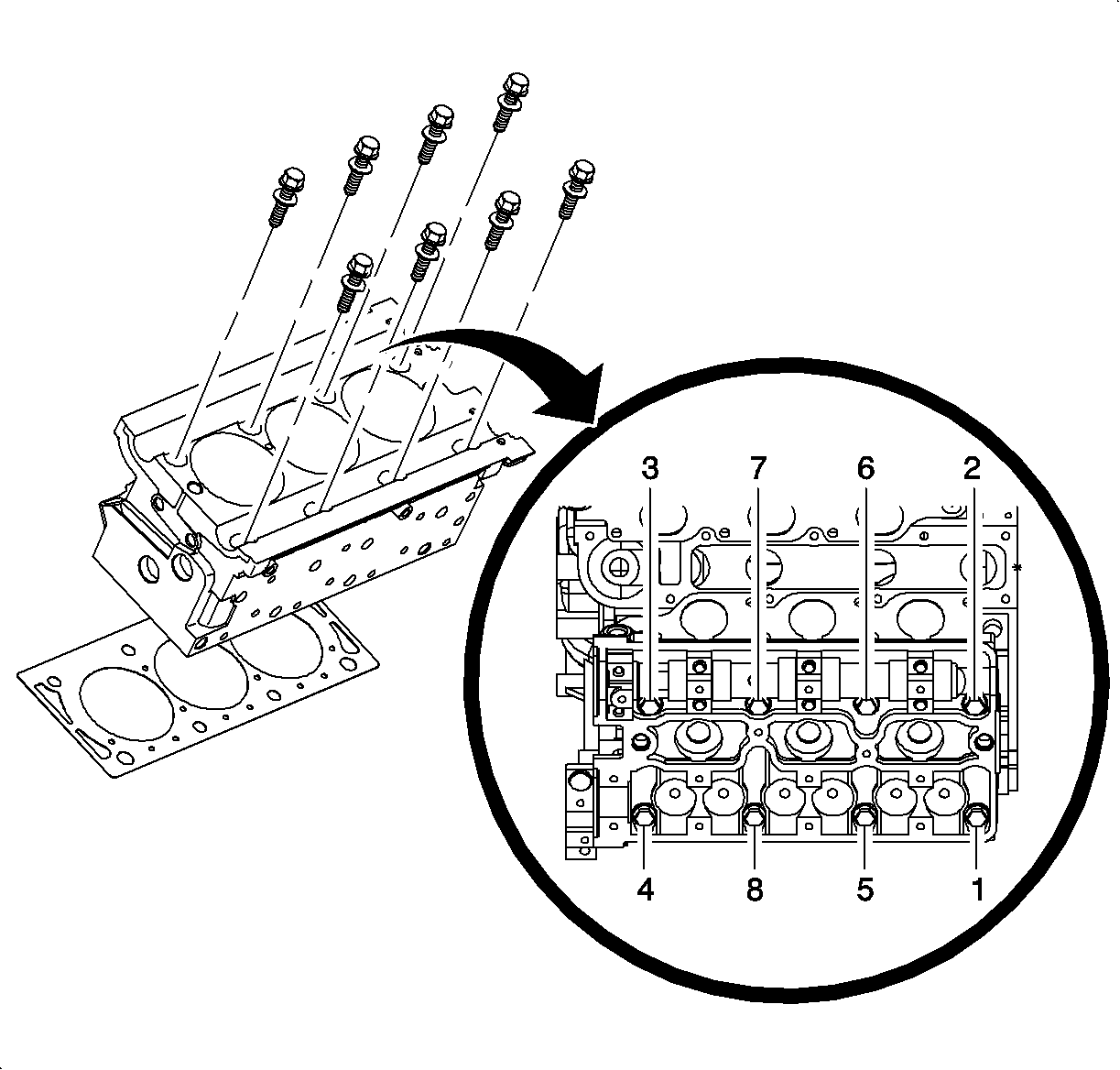
- Loosen the cylinder head bolts in the stages in the sequence shown.
- Remove the cylinder head bolts.
- Remove the cylinder head.
- Remove the cylinder head gasket.
- Clean and inspect the cylinder head and sealing surfaces.
- Remove the exhaust manifold.
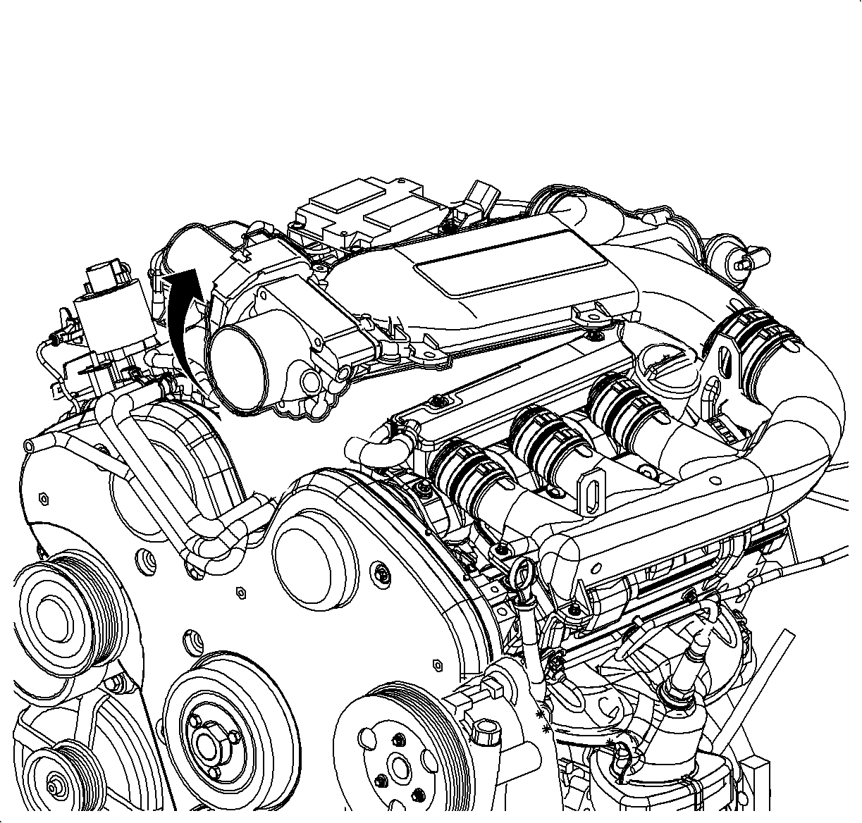
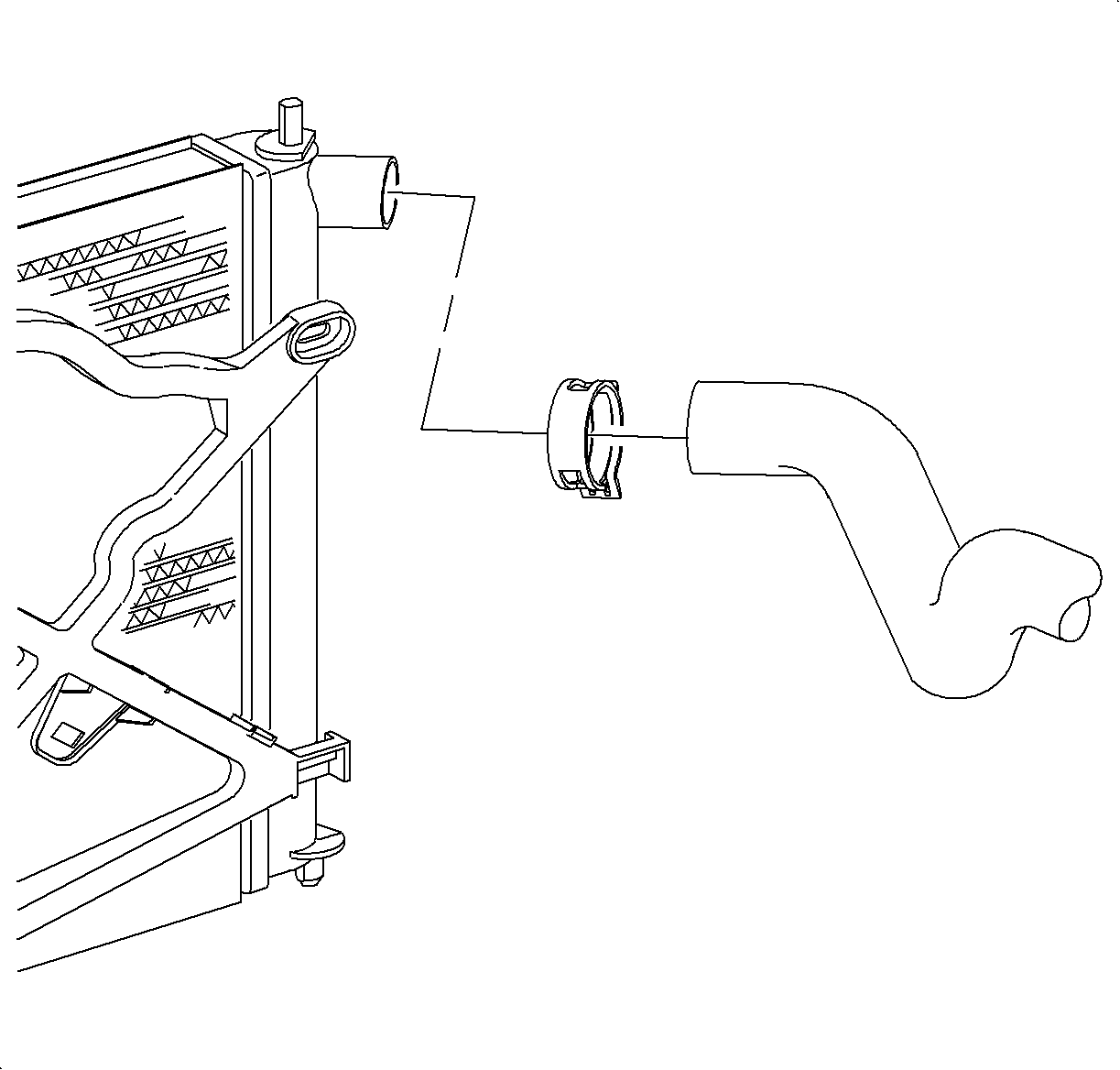
Important: The powertrain must be lifted up in order to remove the coolant extension housing.

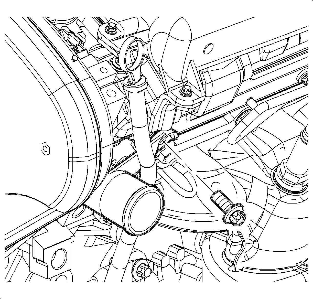
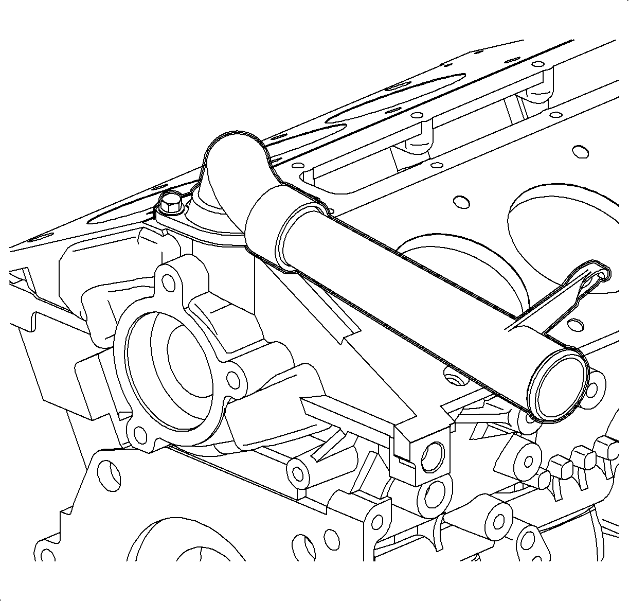
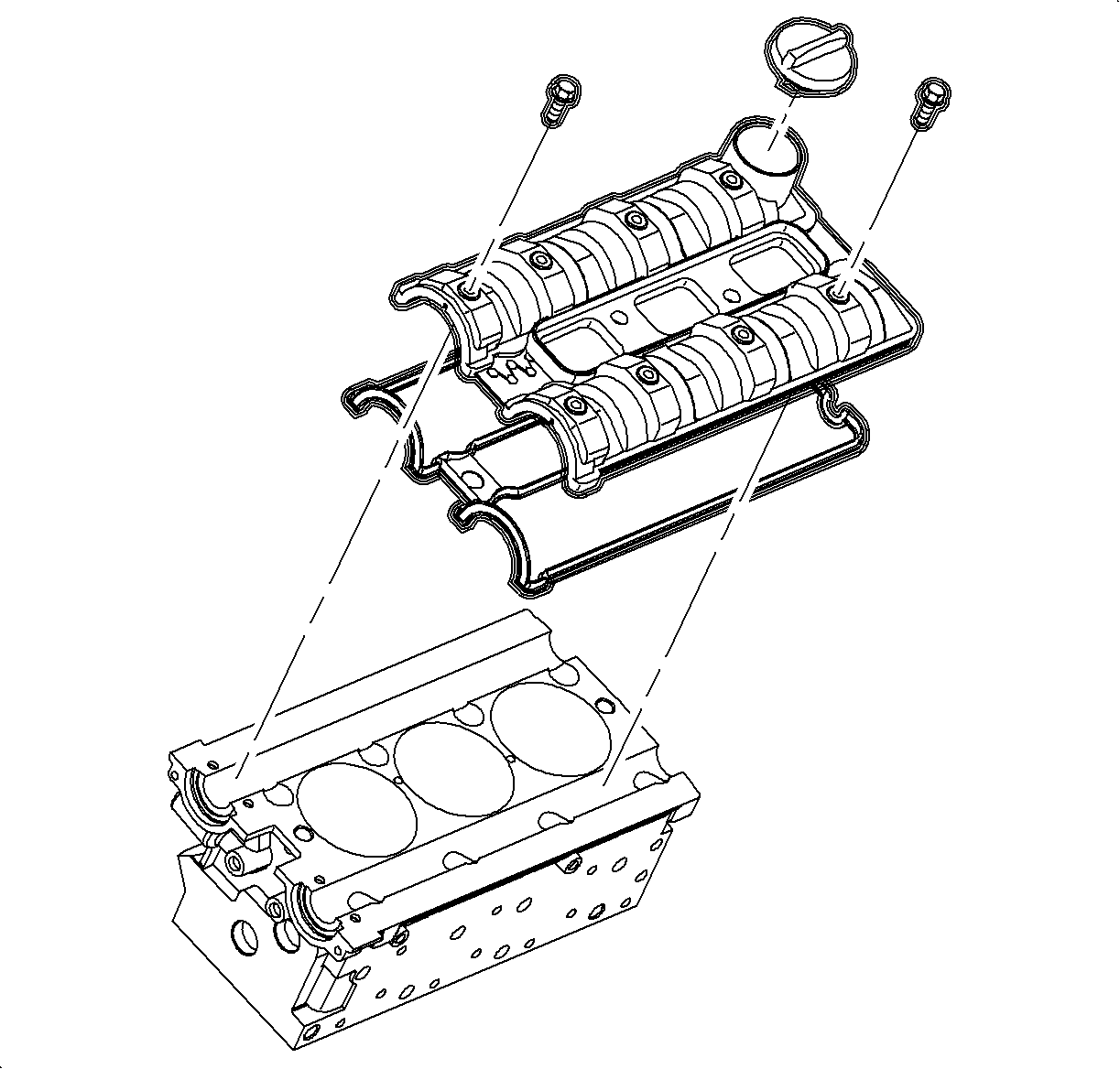


Important: The intake camshaft is marked with the letter A and the exhaust camshaft is marked with the letter E.
Important: It is not necessary to remove the intake camshaft for head bolt access.
Installation Procedure
- Install the exhaust manifold and the new gasket.
- Install the new cylinder head gasket with the part number imprint toward the top of the engine.
- Install the cylinder head to the engine block ensuring the adequate clearance from all the wires, components, etc.
- Install the new cylinder head bolts.
- Replace the 2 sealing rings on the coolant pipe.
- Lubricate the 2 sealing rings with coolant.
- Install the coolant pipe and the engine lift bracket bolt to the cylinder head. Ensure that the bolt passes through all of the attached components.
- Install the upper radiator hose to the coolant pipe.
- Install the upper radiator hose clamp.
- Lower the powertrain and align the front transaxle mount and the mounting bracket using a floor jack.
- Install the front transaxle mount through bolt.
- Remove the floor jack.
- Install the upper radiator hose.
- Install the exhaust camshaft.
- Install the exhaust camshaft sensor electrical connection.
- Install the rear timing belt cover.
- Coat the threaded pin with Threadlocker LOCTITE® 242 compound or equivalent.
- Install the rear timing belt cover bolts.
- Install the rear timing belt threaded pin.
- Install all 4 camshaft gears. Refer to Camshaft Drive Sprocket Replacement .
- Install the timing belt tensioner bracket. Refer to Timing Belt Tensioner Pulley Replacement .
- Install the timing belt. Refer to Timing Belt Replacement .
- Install the front timing belt cover. Refer to Timing Belt Front Cover Replacement .
- Install the front camshaft cover. Refer to Camshaft Cover Replacement .
- Install the coolant bridge and new coolant bridge seals.
- Apply sealing compound LOCTITE® 518, or equivalent, to the sealing surface.
- Install the intake manifold spacer.
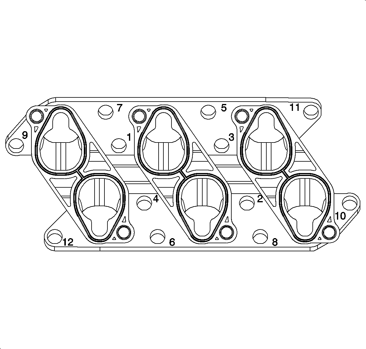
- Install the intake manifold spacer bolts. Tighten the intake manifold spacer bolts in a spiral direction, starting from the inside and working outward.
- Install the intake manifold. Refer to Intake Manifold Replacement .
- Install the intake plenum. Refer to Intake Plenum Replacement .
- Install the intake air cleaner. Refer to Air Cleaner Assembly Replacement .
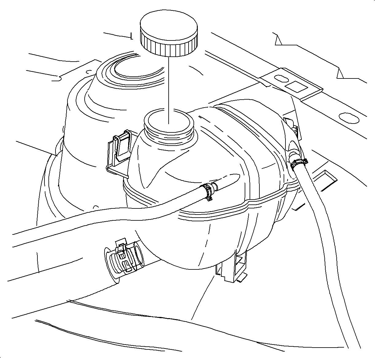
- Refill the coolant.
- Connect the negative battery cable.
Notice: Refer to Fastener Notice in the Preface section.

Tighten
Tighten the exhaust manifold nut to 20 N·m (15 lb ft).

Important: Use the new cylinder head bolts. The required tightening method stretches the bolts to their yield point. Therefore, the cylinder head bolts are not reusable.
Important: Use the SA9140E and the proper tightening sequence to tighten the cylinder head bolts in stages.
Tighten
Tighten the cylinder head bolts to 25 N·m (18 lb ft)
plus 90 degrees plus 90 degrees plus 90 degrees plus 15 degrees.

Tighten
Tighten the coolant pipe/engine lift bracket bolt to 20 N·m (15 lb ft).


Important: The intake camshaft is marked with the letter A and the exhaust camshaft is marked with the letter E.
Important: It is not necessary to remove the intake camshaft for head bolt access.

Tighten
Tighten the rear timing belt cover bolt to 8 N·m (71 lb in).
Tighten
Tighten the rear timing belt cover threaded pin to 10 N·m (89 lb in).


Tighten
Tighten the coolant bridge bolts to 30 N·m (22 lb ft).
Tighten
Tighten the intake manifold spacer bolt 20 N·m (15 lb ft).

Tighten
Tighten the battery terminal bolts to 17 N·m (13 lb ft).
Cylinder Head Replacement Rear
Tools Required
SA9140E Torque Angle Gage
Removal Procedure
- Disconnect the negative battery cable. Refer to Battery Negative Cable Disconnection and Connection in Engine Electrical.
- Remove the intake plenum. Refer to Intake Plenum Replacement .
- Remove the intake air resonator. Refer to Resonator Replacement .
- Remove the intake manifold.
- Remove the intake manifold spacer bolts.
- Remove the intake manifold spacer.
- Remove the coolant bridge.
- Remove the engine ventilation chamber.
- Remove the rear camshaft cover.
- Remove the front timing belt cover. Refer to Timing Belt Front Cover Replacement .
- Remove the timing belt. Refer to Timing Belt Replacement .
- Remove the timing belt tensioner bracket. Refer to Timing Belt Tensioner Pulley Replacement .
- Remove all 4 camshaft gears. Refer to Camshaft Drive Sprocket Replacement .
- Remove the rear timing belt cover. Refer to Timing Belt Rear Cover Replacement .
- Remove the exhaust manifold pipe heat shield.
- Raise the vehicle on a hoist.
- Remove the front exhaust manifold pipe to rear exhaust manifold pipe fasteners.
- Remove the rear exhaust manifold pipe to exhaust manifold pipe nuts.
- Pull down the rear exhaust manifold pipe just enough to remove the gasket.
- Remove the old gasket and discard.
- Drain the coolant.
- Lower the vehicle.
- Remove the EGR to exhaust manifold pipe.
- Remove the exhaust camshaft. Refer to Camshaft Replacement - Left Side and Camshaft Replacement - Right Side .
- Remove the cylinder head bolts.
- Remove the cylinder head.
- Remove the cylinder head gasket.
- Remove the exhaust manifold.
- Clean and inspect the cylinder head and sealing surfaces.


Caution: Ensure that the vehicle is properly supported and squarely positioned. To help avoid personal injury when a vehicle is on a hoist, provide additional support for the vehicle on the opposite end from which the components are being removed.
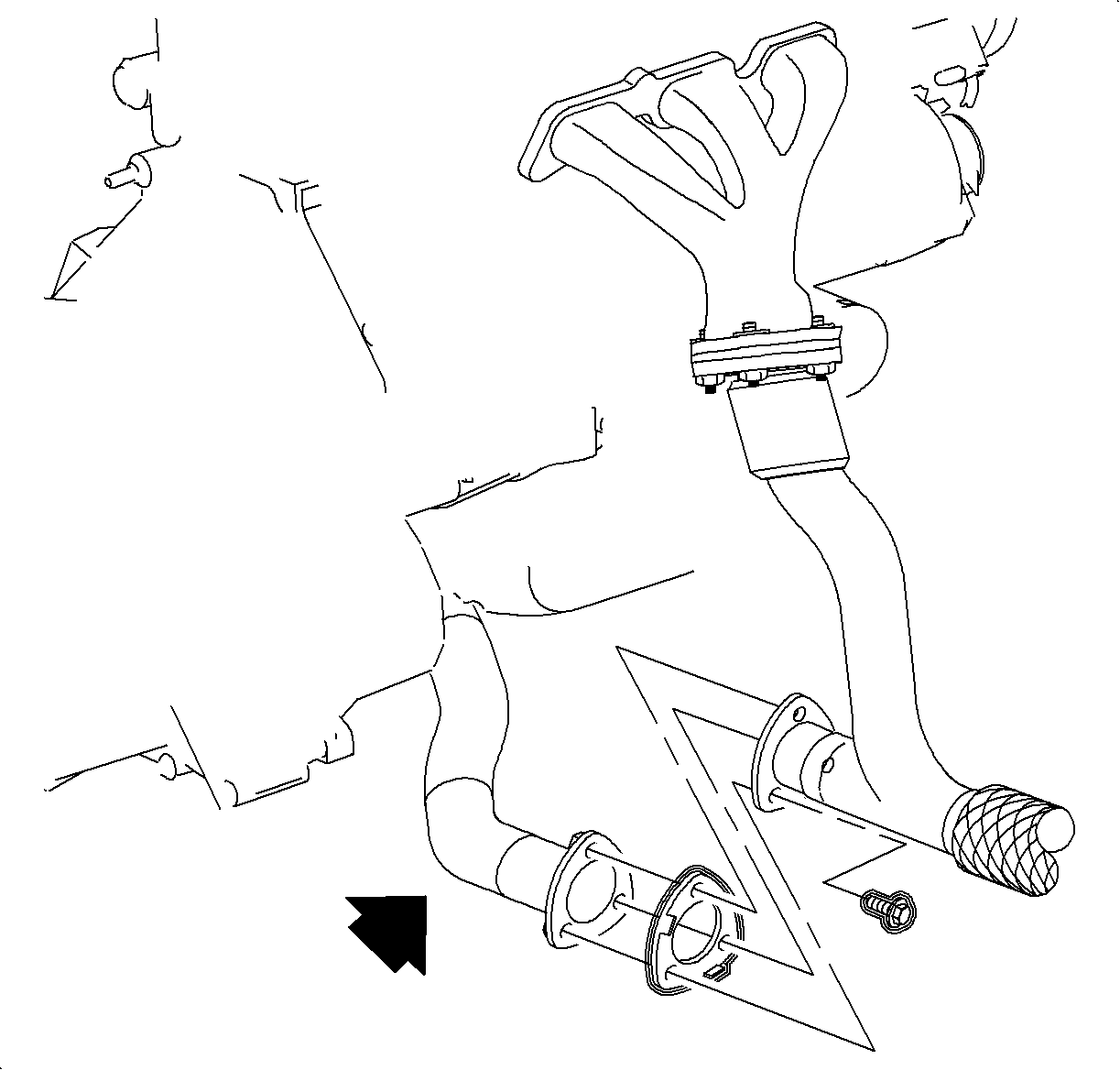
Notice: Avoid excessive movement of the pipe.
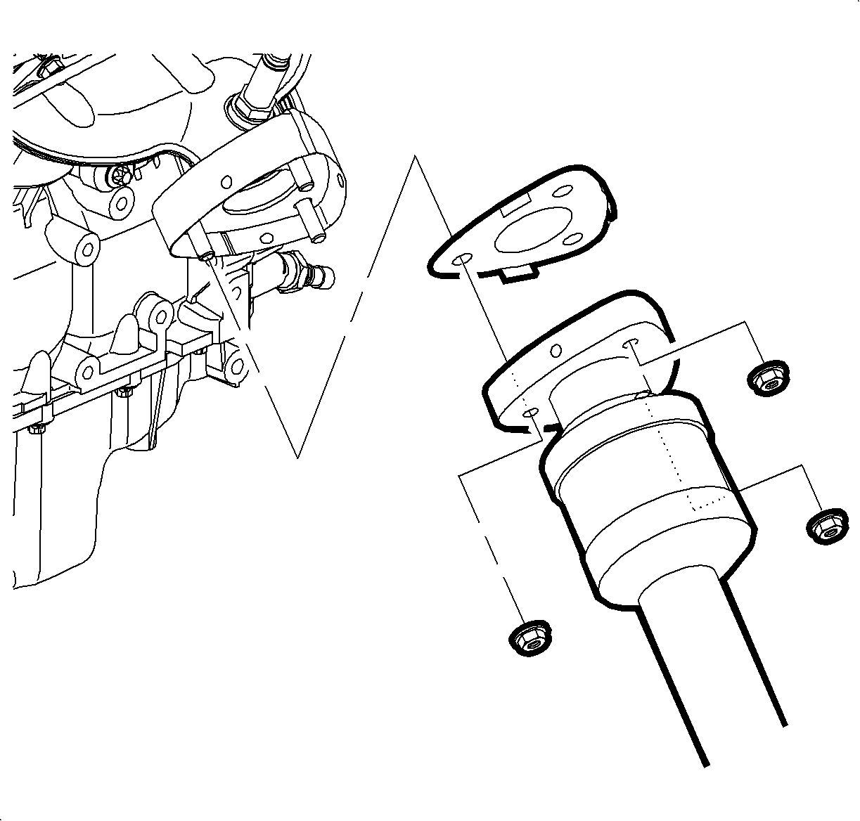

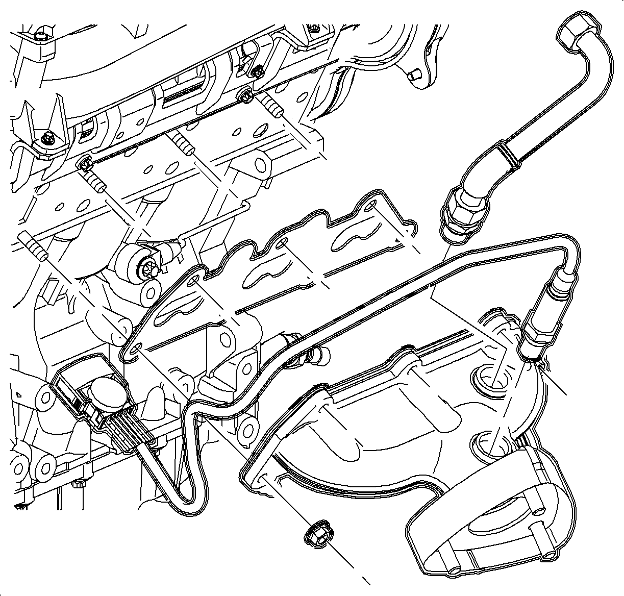

Important: The intake camshaft is marked with the letter A and the exhaust camshaft is marked with the letter E.

Important: Use the loosening sequence to remove the cylinder head.
Important: It is not necessary to remove the intake camshaft for head bolt access.
Installation Procedure
- Install the rear exhaust manifold to the cylinder head. Refer to Exhaust Manifold Replacement in Engine Exhaust.
- Install the new cylinder head gasket with the part number imprint toward the top of the engine.
- Install the cylinder head to engine block ensuring the adequate clearance from all wires, components, etc.
- Install the new cylinder head bolts.
- Install the exhaust camshaft. Camshaft Replacement - Right Side
- Install the rear timing belt cover. Refer to Timing Belt Rear Cover Replacement .
- Install all 4 camshaft gears. Refer to Camshaft Drive Sprocket Replacement .
- Install the timing belt tensioner bracket. Refer to Timing Belt Tensioner Pulley Replacement .
- Install the timing belt. Refer to Timing Belt Replacement .
- Install the front timing belt cover. Refer to Timing Belt Front Cover Replacement .
- Install the rear camshaft cover. Refer to Camshaft Cover Replacement .
- Install the coolant bridge and new coolant bridge seals.
- Apply sealing compound LOCTITE® 518, or equivalent, to the sealing surface.
- Install the engine ventilation chamber.
- Install the intake manifold spacer.
- Install the intake manifold spacer bolts, and apply LOCTITE® 242 to the bolts.
- Tighten the intake manifold spacer bolts in a spiral direction, starting from the inside and working outward.
- Install the intake manifold. Refer to Intake Manifold Replacement .
- Install the intake plenum. Refer to Intake Plenum Replacement .
- Install the intake air cleaner. Refer to Air Cleaner Assembly Replacement .
- Refill the coolant.
- Connect the negative battery cable.
- Install the EGR to exhaust manifold pipe.
- Raise the vehicle.
- Install the exhaust manifold pipe gasket and assembly.
- Install the exhaust manifold pipe nuts.
- Lower the vehicle.
- Start the vehicle and inspect for exhaust leaks.
Notice: Refer to Fastener Notice in the Preface section.
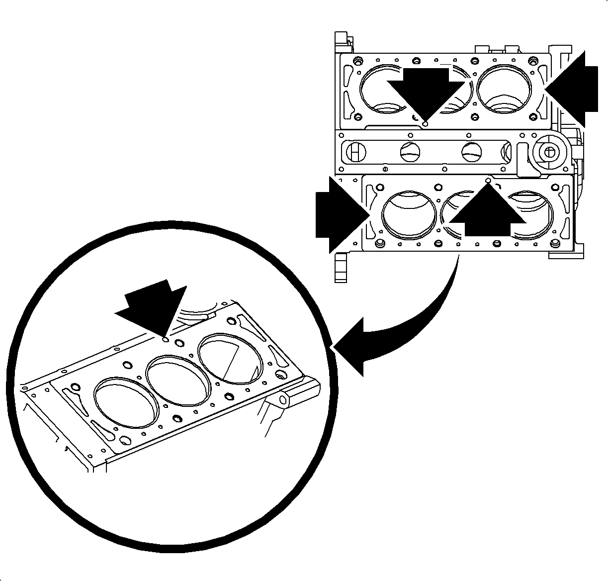
Tighten
Tighten the exhaust manifold nut to 20 N·m
(15 lb ft).

Important: Use the new cylinder head bolts. The required tightening method stretches the bolts to their yield point. Therefore the cylinder head bolts are not reusable.
Important: Use the SA9140E and the proper tightening sequence to tighten the cylinder head bolts in stages.
Tighten
Tighten the cylinder head bolt to 25 N·m
(18 lb ft) plus 90 degrees plus 90 degrees plus 90 degrees
plus 15 degrees.


Tighten
Tighten the coolant bridge bolts to 30 N·m
(22 lb ft).
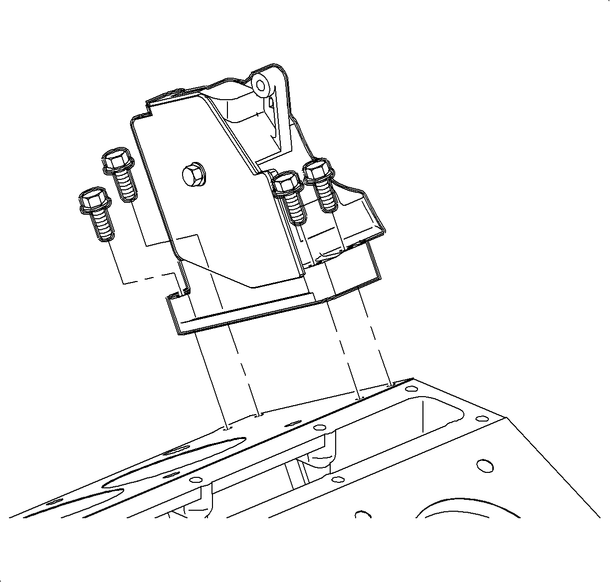
Tighten
Tighten the engine ventilation chamber bolts to
8 N·m (71 lb in).

Tighten
Tighten the intake manifold spacer bolt to 20 N·m
(15 lb ft).

Tighten
Tighten the battery terminal bolts to 17 N·m
(13 lb ft).
Tighten
Tighten the EGR pipe bolts to 25 N·m
(18 lb ft).

Tighten
Tighten the exhaust manifold pipe-to-exhaust manifold
nuts to 30 N·m (25 lb ft).
