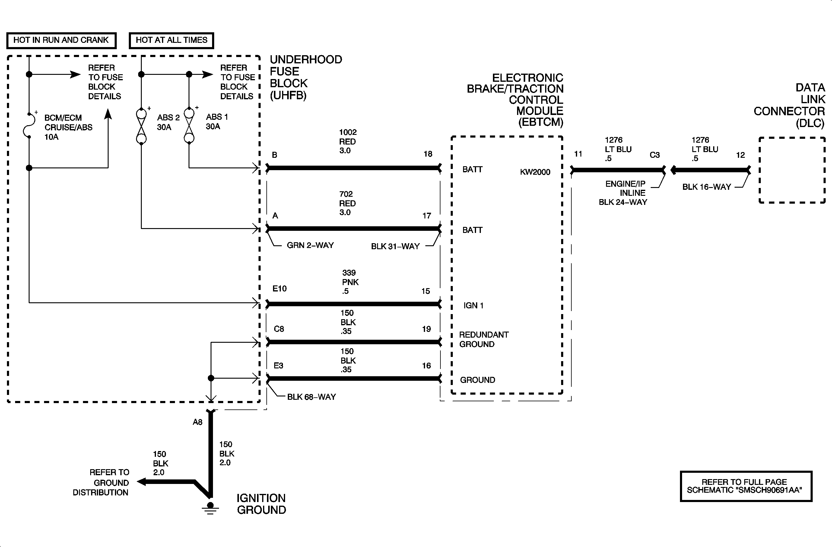
Circuit Description
The antilock brake system (ABS) control module uses a relay to control the valve solenoids. When the ignition is in the Run position, the module energizes the relay winding to switch the battery voltage that supplies the solenoids. The module will disable the relay when the ignition is OFF, or a fault is detected.
Conditions for Running the DTC
The ignition is ON.
Conditions for Setting the DTC
| • | The control module commands the relay ON, but does not sense battery voltage at the solenoids. |
| • | The control module commands the relay OFF, and senses battery voltage at the solenoids. |
Action Taken When the DTC Sets
| • | The ABS telltale turns ON. |
| • | The ABS control module will disable the ABS, the TCS, and the DRP. |
Diagnostic Aids
This relay is inside the ABS control module and is NOT serviceable.
Test Description
The number below refers to step number on the diagnostic table.
Step | Action | Yes | No |
|---|---|---|---|
Schematic Reference: Antilock Brake System Schematics Connector End View Reference: Antilock Brake System Connector End Views | |||
1 | Did you perform the Diagnostic System Check? | Go to Step 2 | |
Does the DTC reset? | Go to Step 3 | Go to Diagnostic Aids | |
3 | Test the battery positive voltage circuit for an open, high resistance, or a short to ground. Refer to Circuit Testing and Wiring Repairs in Wiring Systems. Did you find and correct the condition? | Go to Step 5 | Go to Step 4 |
4 | Replace the Electronic Brake Control Module (EBCM). Refer to Electronic Brake Control Module Replacement . Did you complete the replacement? | Go to Step 5 | -- |
5 |
Does the DTC reset? | Go to Step 2 | System OK |
