For 1990-2009 cars only
Tools Required
| • | J 43600 ACR 2000 Air Conditioning Service Center |
| • | J 39400-A Halogen Leak Detector |
Removal Procedure
- Disconnect the negative battery cable. Refer to Battery Negative Cable Disconnection and Connection in Engine Electrical.
- Recover the refrigerant. Refer to Refrigerant Recovery and Recharging .
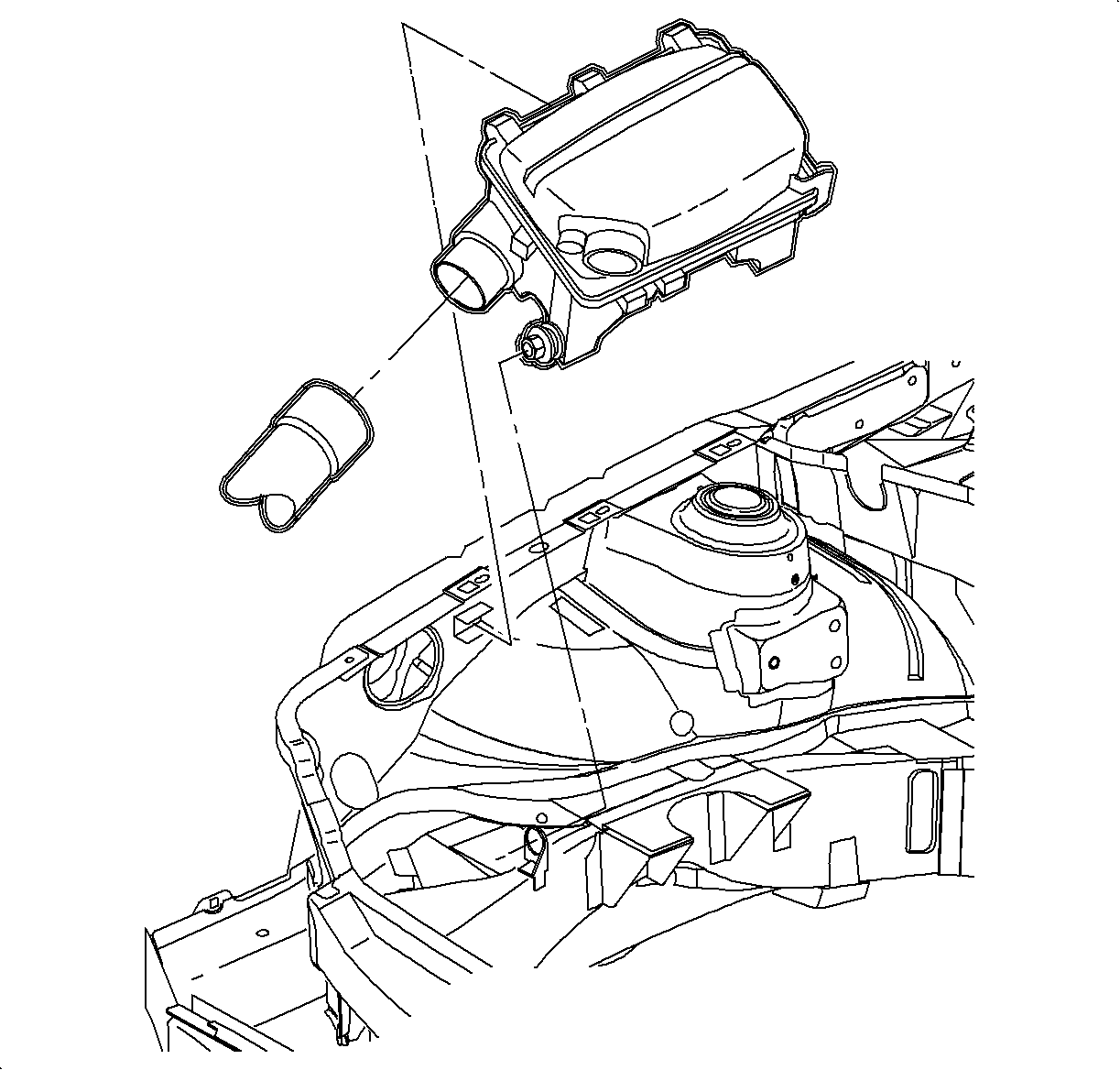
- Remove the air cleaner assembly. Refer to Air Cleaner Assembly Replacement in Engine Controls 2.2L or to Air Cleaner Assembly Replacement in Engine Controls 3.0L.
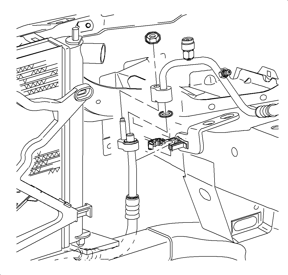
- Remove the fastener that secures the evaporator hose assembly clamp at the engine mount area.
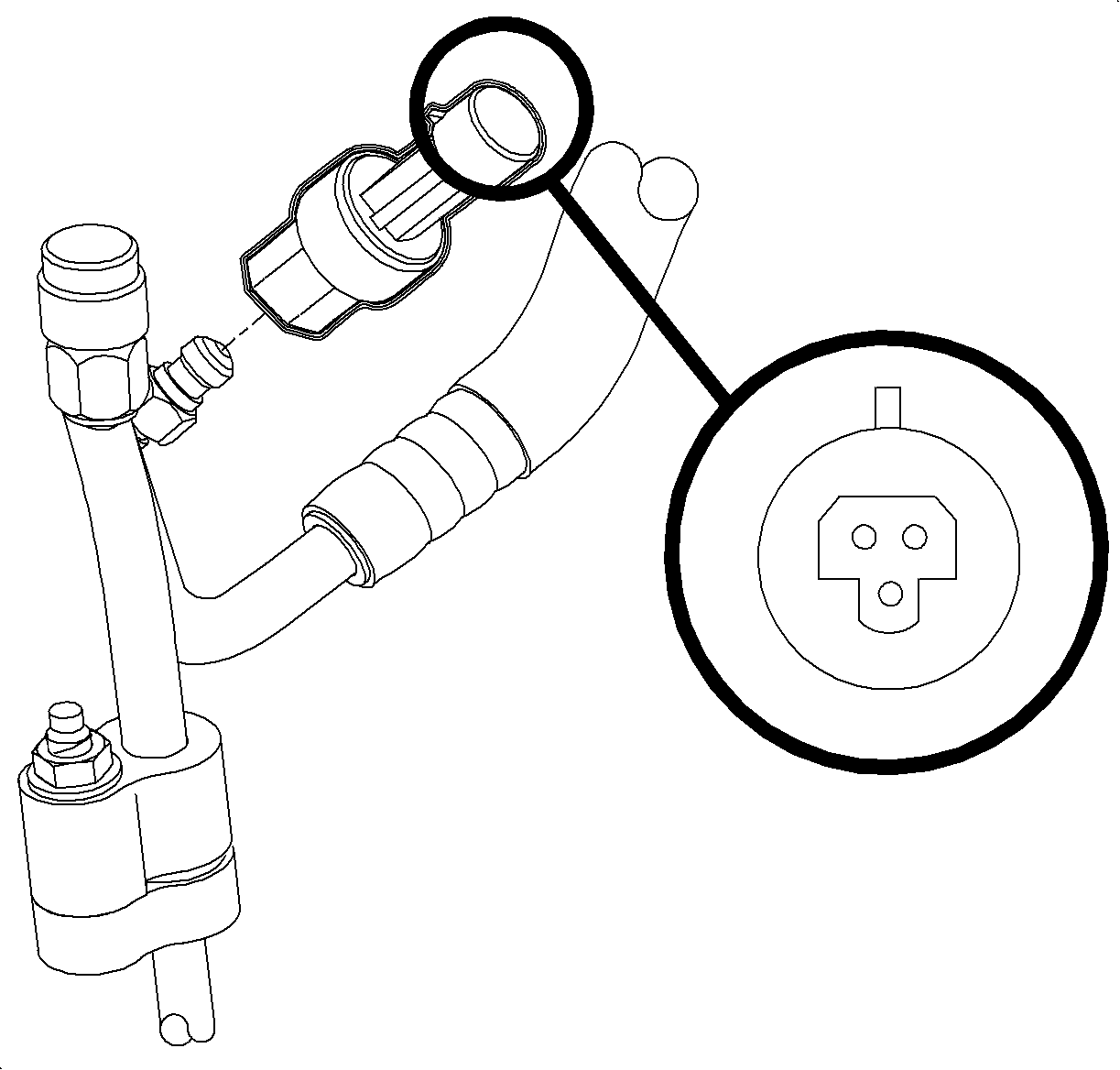
- Disconnect the electrical connector to the refrigerant pressure sensor.
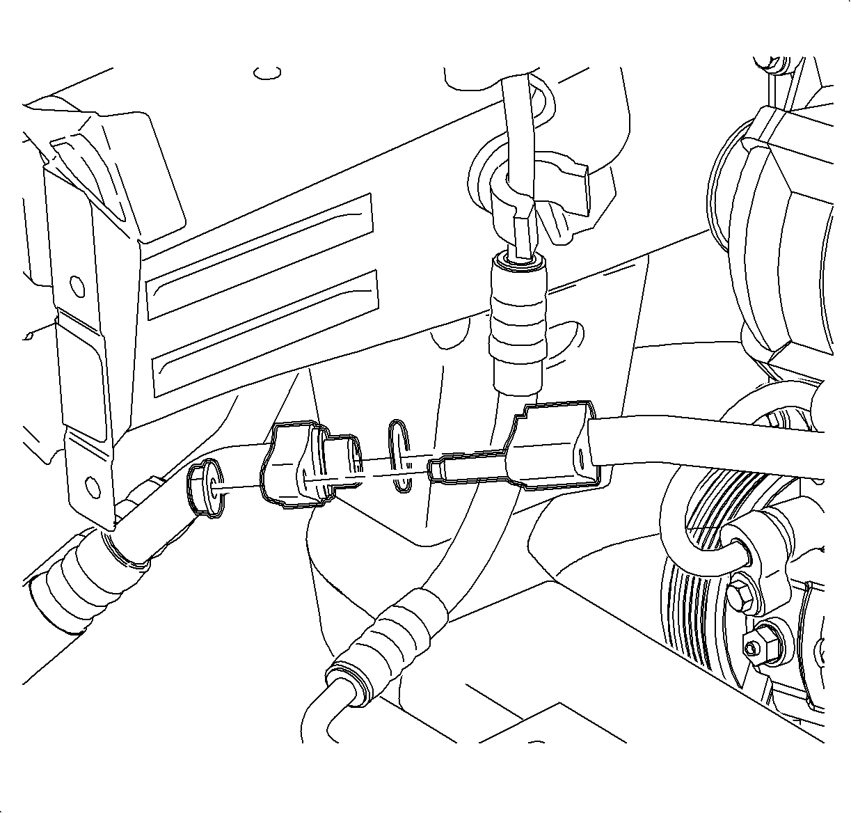
- Remove the nut that secures the evaporator hose assembly to the condenser hose.
- Remove the evaporator hose assembly from the condenser hose.
- Install the cap on the evaporator hose to prevent dirt and moisture entry.
- Raise the vehicle. Refer to Lifting and Jacking the Vehicle in General Information.
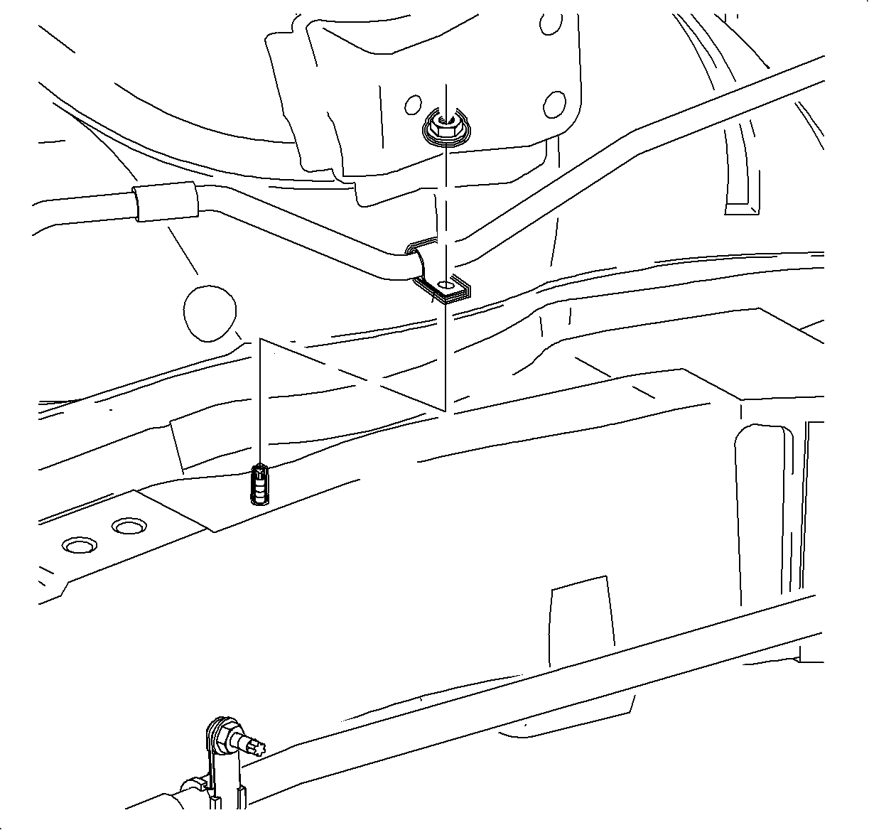
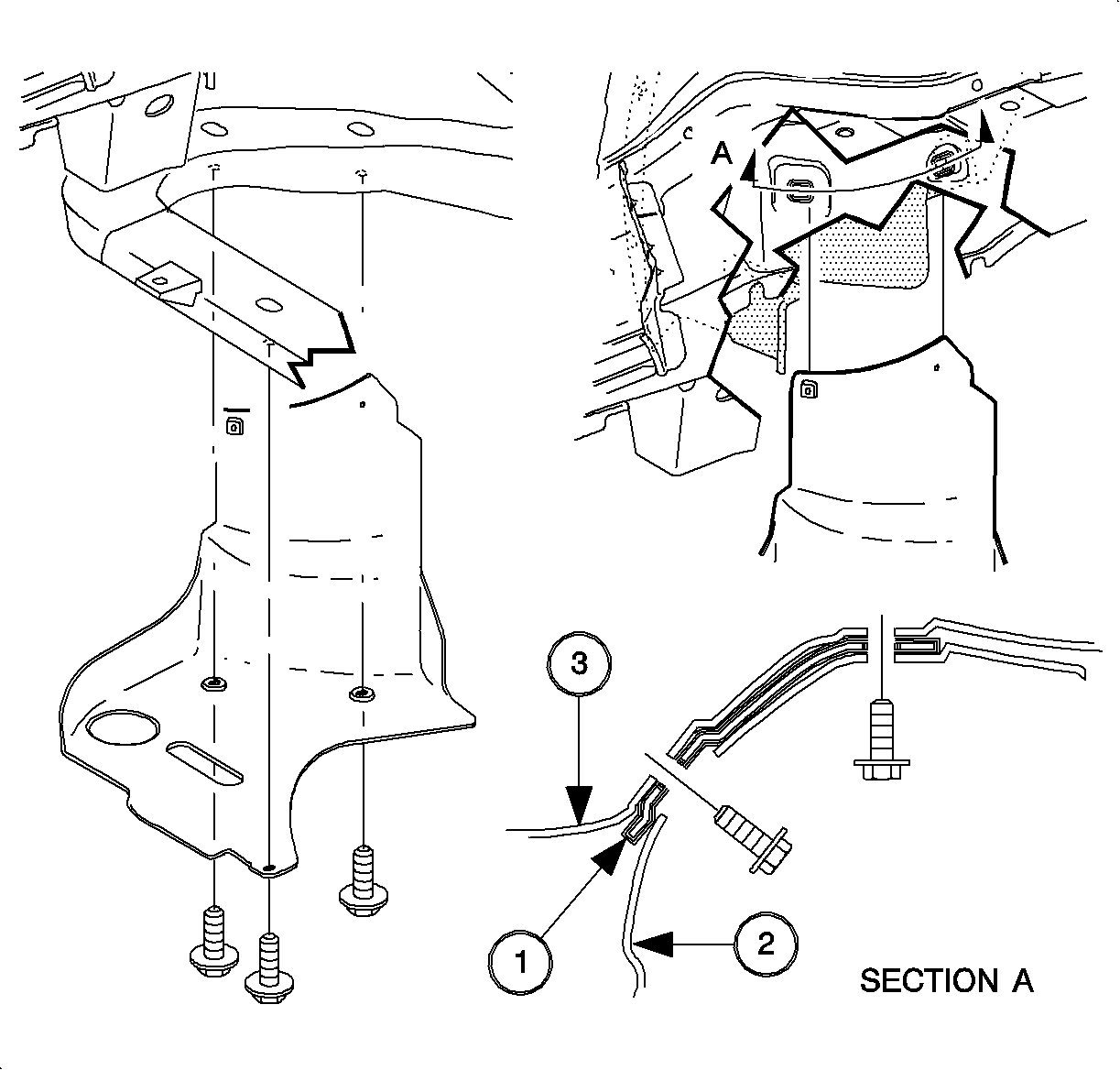
- Remove the splash shield fasteners.
- Remove the splash shield.
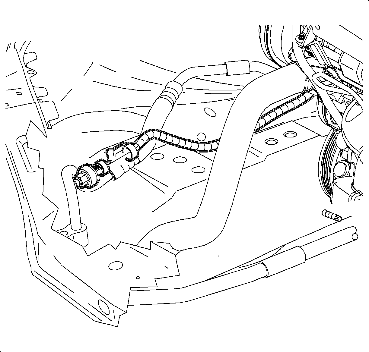
- Remove the nut that secures the evaporator hose assembly to the suction pipe.
- Remove the evaporator hose assembly from the suction pipe.
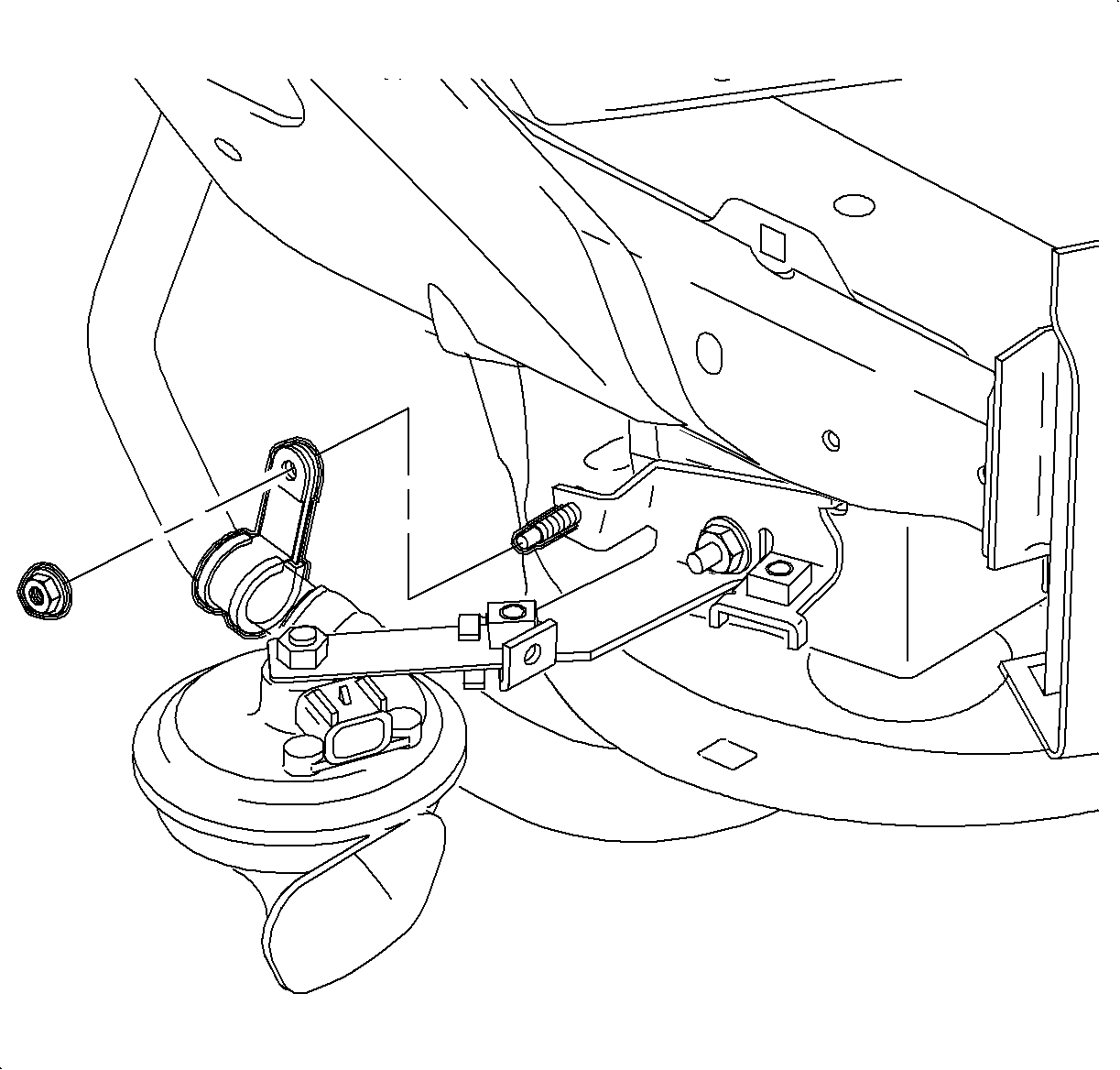
- Remove the bracket clamp that secures the evaporator hose assembly to the horn.
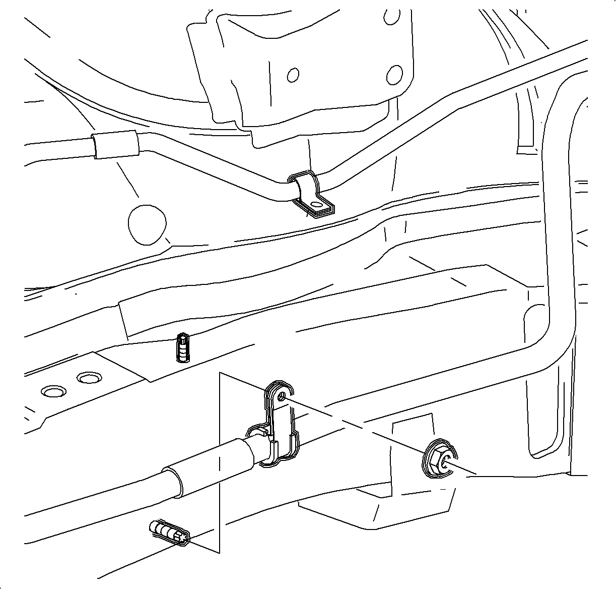
- Remove the nut that secures the evaporator hose assembly clamp at the rail.
- Lower the vehicle.
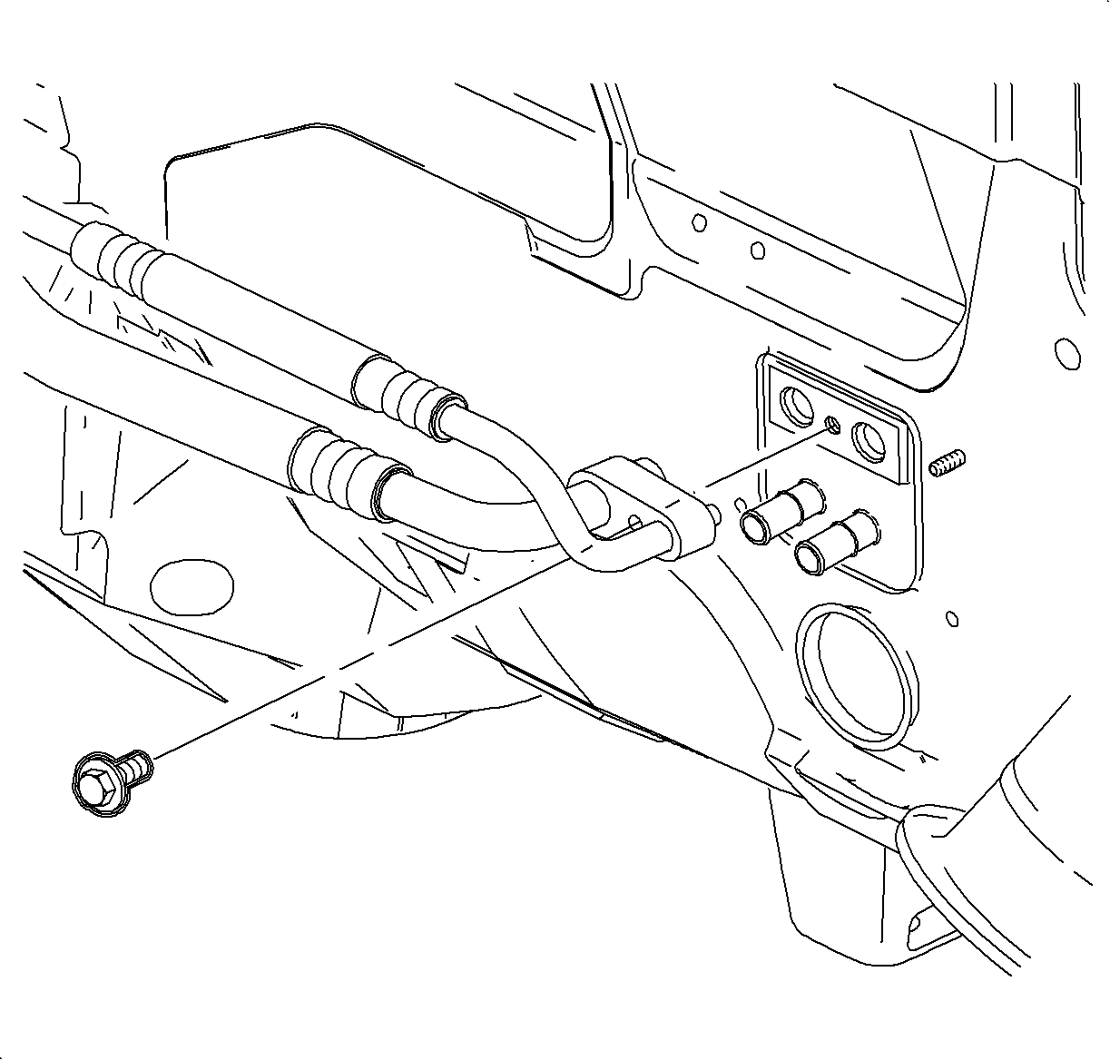
- Remove the bolt that secures the evaporator hose assembly to the thermal expansion valve (TXV).
- Remove the evaporator hose assembly from the TXV.
- Install the cap on the TXV to prevent dirt and moisture entry.
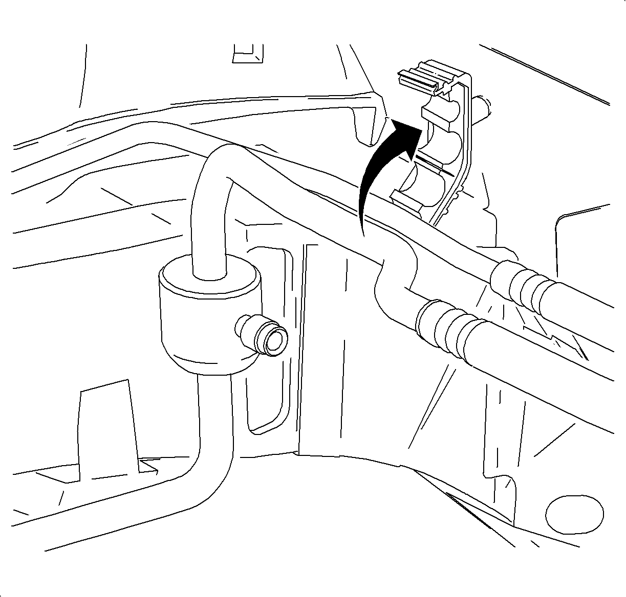
- Remove the evaporator hose assembly from the clamp at the cowl.
- Remove the O2 sensor clip from the evaporator hose assembly.
- Remove the nut that secures the harness bracket to the cowl and open the harness clip.
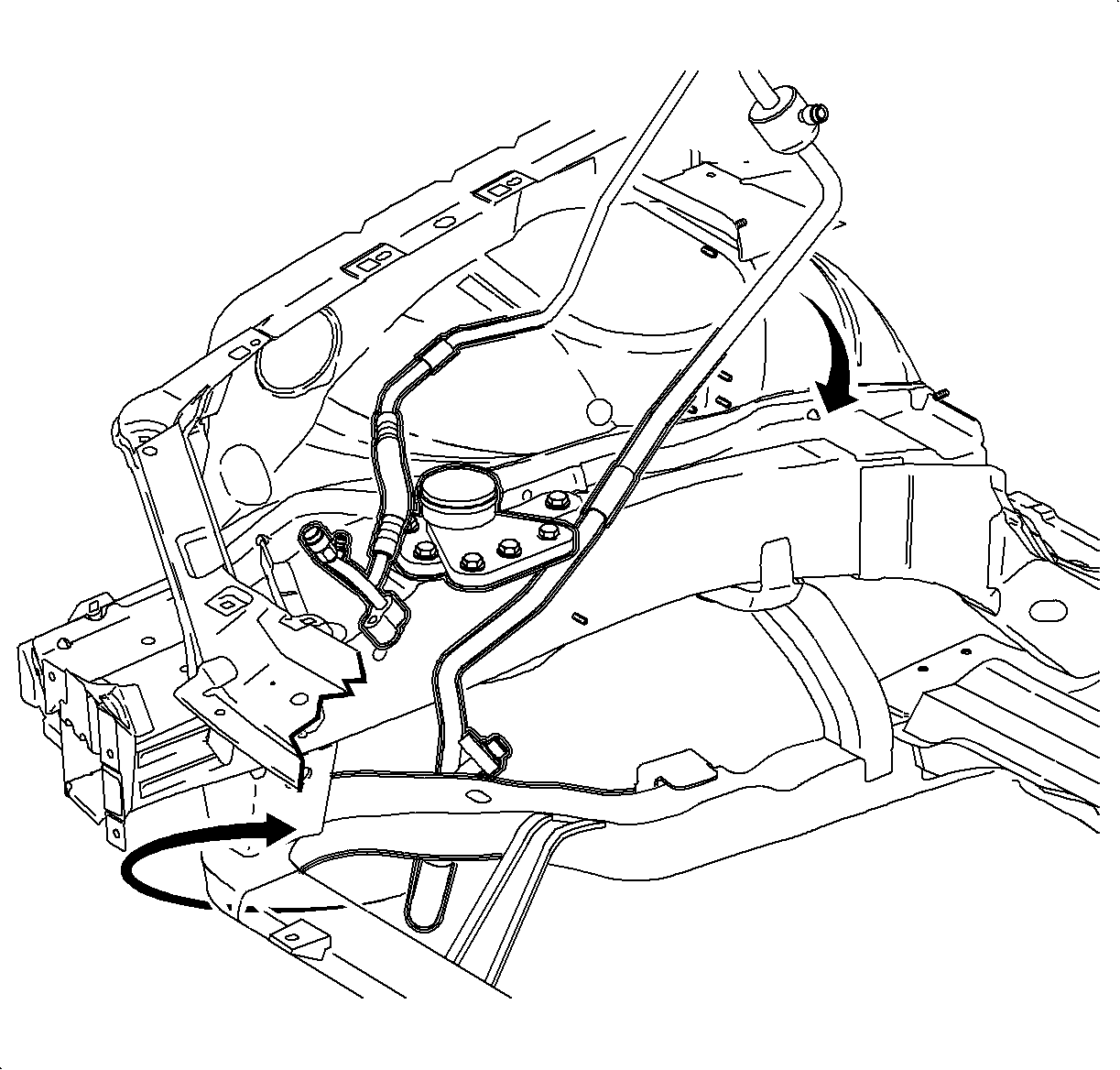
- Remove the evaporator hose assembly from the vehicle.
- Remove refrigerant pressure switch from the evaporator hose assembly.
Caution: Do not remove hoses or lines before system is fully discharged. System may be under pressure and contact with R134a may cause personal injury.
Installation Procedure
- Install the refrigerant pressure switch to the evaporator hose assembly.
- Position the evaporator hose assembly into vehicle.
- Remove the shipping caps from the TXV and the evaporator hose assembly.
- Install new O-rings on the evaporator hose assembly. Refer to O-Ring Replacement .
- Position the evaporator hose assembly to the TXV.
- Install the bolt that secures the evaporator hose to TXV.
- Remove the shipping cap from the evaporator hose assembly and from the condenser hose.
- Install a new seal washer to the evaporator hose assembly. Refer to Sealing Washer Replacement .
- Install the nut that secures the evaporator hose to the condenser hose.
- Install the evaporator hose assembly into the clamp at the cowl.
- Install the oxygen sensor harness clip onto the evaporator hose assembly.
- Close the steel harness clip and install the nut.
- Install the evaporator hose assembly clamp at the mount area.
- Raise the vehicle.
- Install a new seal washer to the evaporator hose assembly. Refer to Sealing Washer Replacement .
- Install the nut that secures the evaporator hose to the suction pipe.
- Install the nut that secures the evaporator hose assembly clamp to the horn bracket.
- Install the evaporator hose assembly clamp at the rail and install the nut.
- Install the lower cradle splash shield (1).
- Install the splash shield fasteners.
- Lower the vehicle.
- Connect the refrigerant pressure sensor electrical connector.
- Install the air cleaner assembly. Refer to Air Cleaner Assembly Replacement in Engine Controls 2.2L or to Air Cleaner Assembly Replacement in Engine Controls 3.0L.
- Connect the negative battery cable. Refer to Battery Negative Cable Disconnection and Connection in Engine Electrical.
- Evacuate and recharge the A/C system. Refer to Refrigerant Recovery and Recharging .
- Using J 39400-A , leak test the fittings of the component.
Notice: Refer to Fastener Notice in the Preface section.
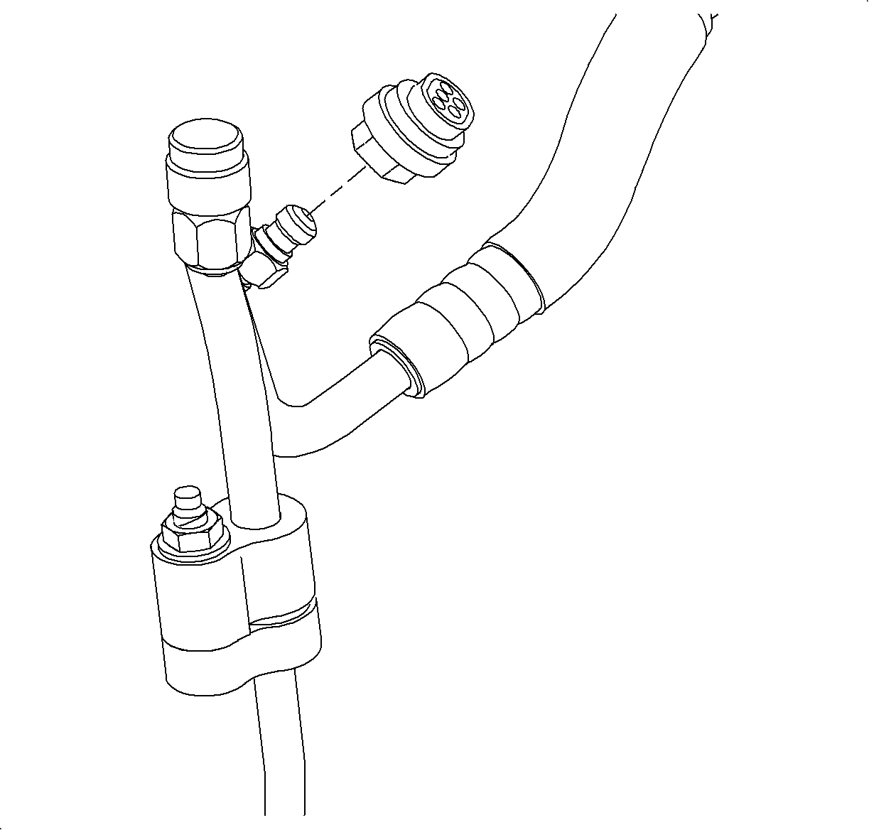
Tighten
Tighten the switch to 7 N·m (62 lb in).

| • | Position the evaporator hose inside of the wiring harness and outside of the fuel lines. |
| • | Position the evaporator hose rearward of the wiring harness at the front of the dash with the oxygen sensor harness behind the evaporator hose. |

Tighten
Tighten the bolt to 7 N·m (62 lb in).

Tighten
Tighten the nut to 12 N·m (106 lb in).

Tighten
Tighten the nut to 6 N·m (53 lb in).

Tighten
Tighten the nut to 5 N·m (44 lb in).

Tighten
Tighten the nut to 12 N·m (106 lb in).

Tighten
Tighten the nut to 10 N·m (89 lb in).

Tighten
Tighten the nut to 5 N·m (44 lb in).

Tighten
Tighten the fasteners to 5 N·m (44 lb in).


