Tools Required
SA9127E Gage Bar Set
J 44855 Fuel Line Disconnect Set
Removal Procedure
- Disconnect the negative battery cable.
- Disconnect the intake air temperature (IAT) sensor connector.
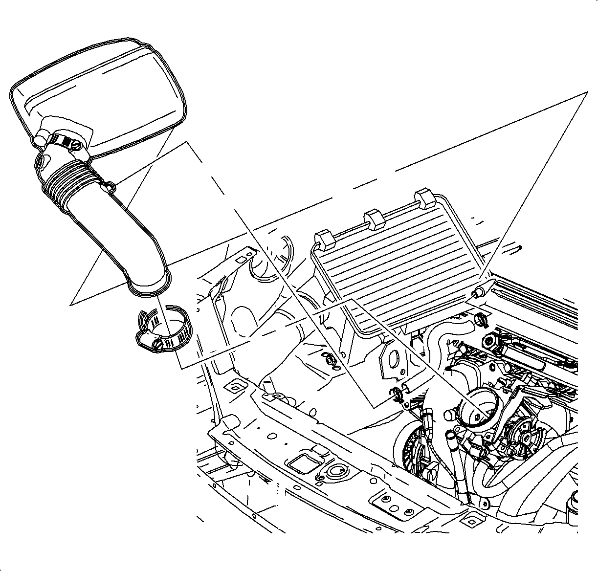
- Loosen the clamp at the air cleaner assembly.
- Remove the push pin attachment from the outlet resonator/duct assembly to support bracket.
- Loosen the clamp at the throttle body assembly.
- Disconnect the PCV fresh air vent hose at the cam cover.
- Remove the outlet resonator/duct assembly.
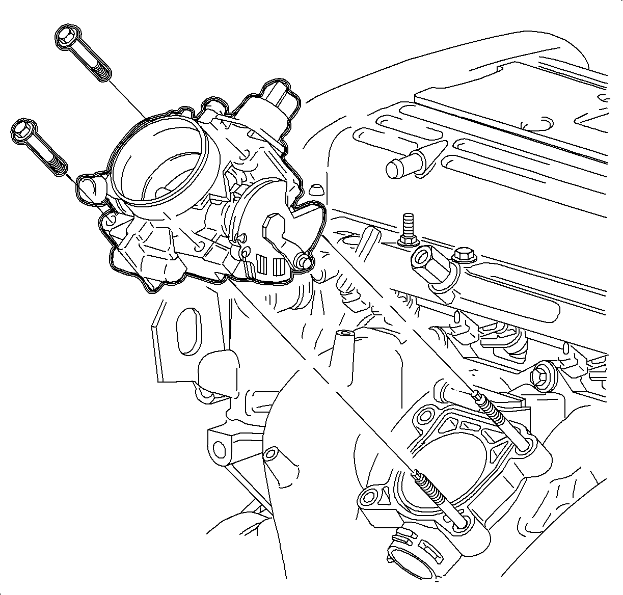
- Remove the throttle cable from the throttle body cam.
- Using shop air, blow off dirt and dust near the fuel injector ports.
- Remove the throttle body and place a rag in the throttle body opening.
- Relieve the fuel system pressure. Refer to Fuel System Diagnosis .
- Disconnect the SA9127E after the pressure has been relieved.
- Position the engine harness away from the fuel rail assembly.
- Disconnect the fuel rail bracket and nut at the rear of cam cover.
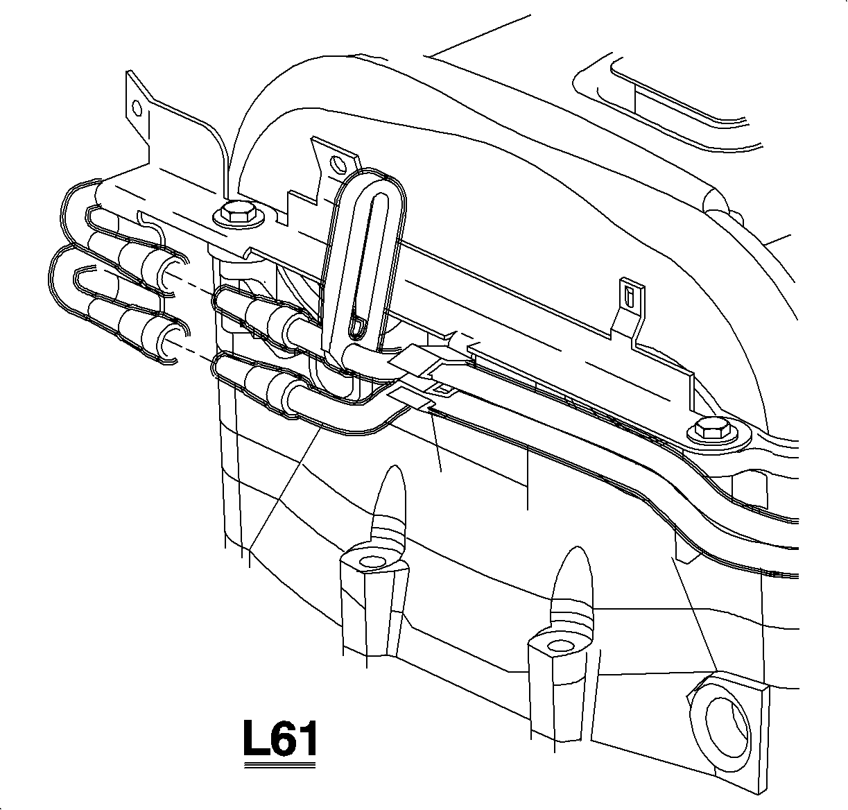
- While supporting the fuel rail assembly with an open-end wrench, loosen the transfer line fitting at the fuel rail.
- Position the fuel line away from the rail assembly without disconnecting the degas hose.
- Disconnect the electrical connectors at the fuel injectors.
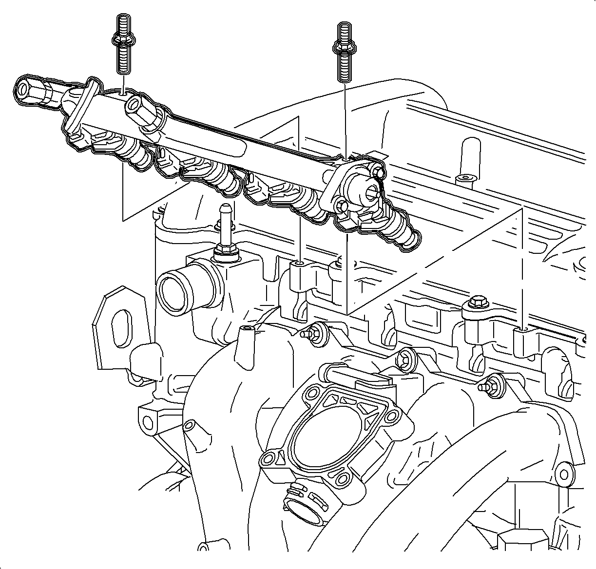
- Remove the fuel rail assembly attachment bolts.
- Remove the fuel rail assembly by carefully pulling the rail backward and upward to remove the injectors from the cylinder head.
- Move the fuel rail assembly rearward while slightly rotating it to remove the fuel rail assembly.
- Remove the fuel injector retaining clips.
- Remove the fuel injectors from the fuel rail.
- Remove and discard all injector O-ring seals by using a small pick.

Caution: Whenever fuel line fittings are loosened or disconnected, wrap a shop cloth around the fitting to collect fuel. Place the cloth in an approved container.
Notice: Use care in removing the fuel rail assembly to prevent damage to the electrical connector terminals and spray tips. The fuel injector is serviced as a complete assembly only. Support fuel after fuel rail is removed in order to avoid damaging fuel rail components. Since it is electrical, it should not be immersed in any cleaner.
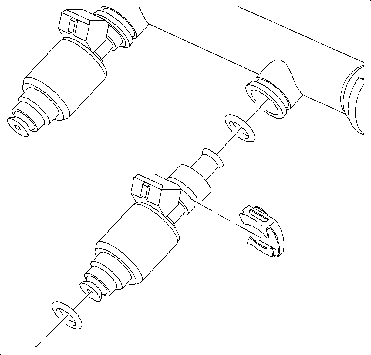
Notice: When cleaning or servicing the fuel rail, care must be taken to assure that the plastic fuel rail surfaces that mate to the injector O-rings are not scratched.
Important: Whenever the fuel rail is removed for service, the upper and lower O-ring seals must be replaced. The injectors can be serviced individually if required.
Installation Procedure
- Transfer the components to new the fuel rail if the rail is being replaced.
- Install the new upper and lower O-ring seals to the injectors.
- Install the injectors to the fuel rail assembly.
- Install the isolators with new seals to the injectors.
- Install the injector retaining clip.
- Install the fuel rail to the cylinder head.
- Install the fuel rail bolts.
- Re-position the fuel line assembly.
- Install the fuel line bracket and bracket bolt.
- Connect the fuel rail bracket and nut to the cylinder head.
- Connect the fuel line to the transfer line.
- Insert the fuel transfer line into the fuel line connection. An audible click noise should be heard.
- Remove the rag from the throttle body opening.
- Reinstall the throttle body.
- Install the outlet resonator/duct assembly into position.
- Install the throttle cable.
- Connect the PCV fresh air bent hose assembly.
- Tighten the clamp at the throttle body assembly.
- Position the outlet resonator/duct assembly up with the support bracket and install the push pin.
- Tighten the clamp at the air cleaner assembly.
- Connect the intake air temperature (IAT) sensor connector.
- Connect the negative battery cable.


Important: Lubricate the O-rings at the injector isolators prior to installing the injectors into the cylinder head.
Notice: Refer to Fastener Notice in the Preface section.
Tighten
Tighten the fuel rail-to-cylinder head - L61 to 10 N·m (89 lb in).

Notice: An open-end wrench must be used to support the fuel line to rail connection during loosening/tightening to avoid damaging the fuel rail assembly.
Tighten
Tighten the transfer line fitting-to-fuel rail - L61 to 10 N·m
(89 lb in).
Tighten
Tighten the fuel line bracket bolt - L61 to 10 N·m (89 lb in).
Important: To ensure proper connection and to fully seat the retaining tabs, lightly pull apart the connection.

Tighten
Tighten throttle body bolts to 10 N·m (89 lb in).
Tighten
Tighten throttle body nuts to 10 N·m (89 lb in).

Tighten
Tighten the battery terminal bolts to 17 N·m (13 lb ft).
