Shifter Knob Loose or Detached From Shift Control Lever (Secure Shifter Knob with Adhesive and Fastener)

| Subject: | Shifter Knob Loose or Detached From Shift Control Lever (Secure Shifter Knob with Adhesive and Fastener) |
| Models: | 2005 Chevrolet Cobalt SS Supercharged |
| 2004-2005 Saturn ION Red Line |
| with 5-Speed Manual Transaxle (RPO MU3) |
This bulletin is being revised to delete the WPC form. Parts are now available from GMSPO and Saturn SPO. Please discard Corporate Bulletin Number 05-07-29-006 (Section 07 - Transmission/Transaxle).
Condition
Some customers may comment that the shift control knob (shifter knob) may be loose or detached from the shift control lever.
Cause
The interference fit between the shift control knob and the shift control lever may allow the shift control knob to become loose or detached.
Correction
Secure the original equipment or new service shift control knob to the shift control lever using adhesive and a self-tapping fastener.
Service Procedure
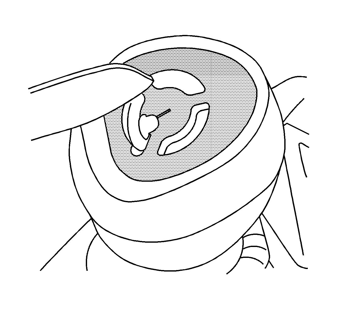
- Carefully remove the emblem from the original equipment shift control knob. Save this emblem for re-use if retaining the original equipment shift control knob or for re-use on the new service shift control knob, if applicable.
- Place the shift control knob back on the shift control lever. Ensure that the shifter knob is correctly oriented.
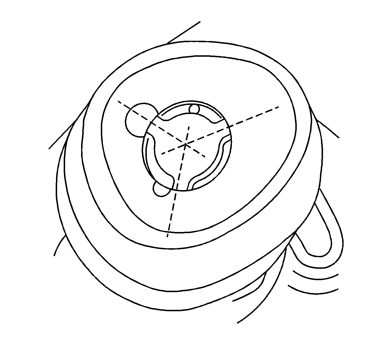
- Cut the three plastic legs on the shift control knob face and remove the central plastic area.
- Locate the center of the shift knob face and mark with center punch.
- Drill a 4.76 mm (0.1875 in [3/16 in]) hole through the shift control knob face and into the shift control lever to a depth of 14.5 mm (0.57 in).
- Countersink chamfer of hole to allow the fastener to be flush with the shift control knob face. Use a 8.73 mm (0.344 in [11/32 in]) drill bit to countersink.
- Remove the shift control knob from the shift control lever.
- Apply accelerant to the top 5 mm (0.2 in) of the shift control lever shaft first - then apply adhesive to this area. Keep a clean dry shop cloth readily available to prevent any drips or runs.
- Seat the shift control knob over the shift control lever. Ensure that the spring and the foam rings are correctly seated. Ensure that the shift control knob is correctly oriented.
- Place a M5x12 self-tapping screw into the hole and tighten the screw until the fastener head is flush
- Position and fit the emblem over the shift control knob.
- Vacuum and clean any debris.
Important: Make sure the leather boot is still in place around the shift control lever base in order to prevent drilling debris from falling into the shifter mechanism.
Important: Re-use the original equipment shifter knob whenever possible. Only use a new service shifter knob if the original equipment knob is damaged or missing.
Important: The service shifter knob may feel slightly "looser" than the production part. This is a normal characteristic. Do NOT replace the entire shift control assembly for this condition.


Diameter
4.76 mm (0.1875 in [3/16 in])
Depth
14.5 mm (0.57 in)
Top diameter
10.4 mm (0.41 in)
Notice: Do not allow any adhesive to drip or run lower than the top 5 mm (0.2 in) of the shift control lever shaft. If the adhesive comes into contact with the reverse lockout mechanism, the reverse lockout may be rendered inoperative.
Important: Use *Loctite® Accelerant 7471 or 7649 primer and *Loctite® Threadlocker 270™ thread locking adhesive.
Notice: Use the correct fastener in the correct location. Replacement fasteners must be the correct part number for that application. Fasteners requiring replacement or fasteners requiring the use of thread locking compound or sealant are identified in the service procedure. Do not use paints, lubricants, or corrosion inhibitors on fasteners or fastener joint surfaces unless specified. These coatings affect fastener torque and joint clamping force and may damage the fastener. Use the correct tightening sequence and specifications when installing fasteners in order to avoid damage to parts and systems.
Tighten
Tighten the fastener to 5.68 N·m (50 lb in).
Important: Do not operate the lever until the adhesive has dried (at least 30 minutes ).
*We believe this source and their products to be reliable. There may be additional manufacturers of such products. General Motors does not endorse, indicate any preference for or assume any responsibility for the products from this firm or for any such items which may be available from other sources.
Parts Information
Part Number | Description | Qty |
|---|---|---|
11569585 | M5x12 Self-Tapping Screw | 1 |
Warranty Information
For vehicles repaired under warranty, use:
Labor Operation | Description | Labor Time |
|---|---|---|
C9738* | Knob, Control and/or Shift - One and/or All -- Replace | 0.3 hr |
*This is a unique labor operation number for bulletin use only. This number will not be published in the Labor Time Guide. | ||
