| Table 1: | Underhood Fuse Block (UHFB) Minifuses/J-Case Fuses |
| Table 2: | Underhood Fuse Block (UHFB) Relays |
| Table 3: | Instrument Panel Fuse Block Minifuses |
The wiring circuits in your vehicle are protected from short circuits by a combination of fuses. This greatly reduces the chance of fires caused by electrical problems.
There are two fuse blocks in your Saturn vehicle -- the "underhood fuse block" and the "instrument panel fuse block." These fuse blocks are used to identify and check fuses and relays.
Instrument Panel Fuse Block

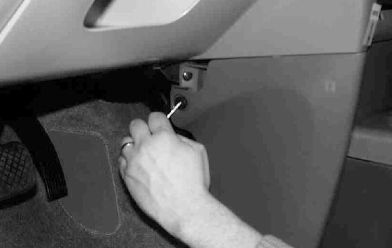
The instrument panel fuse block is located near the driver's side right leg. To remove the fuse panel cover and access the fuses and relays, loosen the screw on the cover and remove the cover.

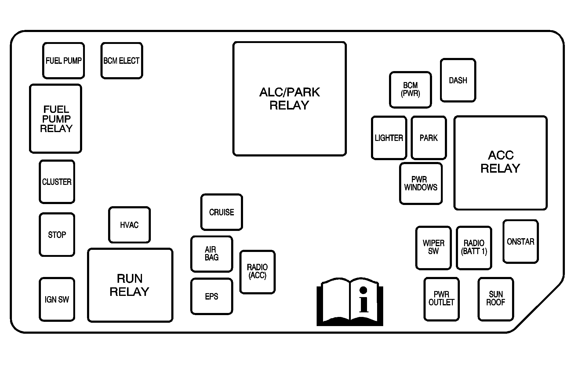
Refer to the Fuse and Relay Usage Chart on the inside of the fuse panel cover to identify the fuses and relays.
Underhood Fuse Block

The underhood fuse block is located in the rear right portion of the engine compartment. To identify and check fuses and relays, refer to the Fuse and relay Usage Chart.
Check the fuse by looking at the silver colored band inside the fuse. If the band is broken or melted, replace the fuse. Be sure you replace a bad fuse with a new one of the same amperage. Always reinstall the fuse block cover after use.
The following chart lists the minifuses, located in the underhood fuse block, and the system they control.
Note: A label is provided on the fuse block cover for fuse layout.
Fuse | Color (AMP) | System |
|---|---|---|
ABS Fuse 22 | Yellow (20) | ABS/Traction Control Module |
ABS Fuse 40 | J-Case (40) | ABS/Traction Control Module |
ABS Fuse 8 | Red (10) | ABS/Traction Control Module |
A/C Fuse 5 | Red (10) | A/C Clutch Relay |
Back-Up Fuse 15 | Red (10) | PRNDIL, Back-Up Switch |
COOLING FAN Fuse 45 | J-Case (30) | Cooling Fan Relay Mini-Relay |
CRANK Fuse 46 | J-Case (30) | PCM Cont (CRANK) Mini-Relay |
ECM Fuse 9 | Red (10) | Engine Control Module |
ECM/TCM Fuse 1 | Red (10) | Engine Control Module, Transmission Control Module |
EPS 1 Fuse 43 | J-Case (30) | Electrical Power Steering |
EPS 2 Fuse 42 | J-Case (30) | Electrical Power Steering |
ERLS Fuse 10 | Red (10) | Can. Purge Solenoid, Can. Vent Solenoid, Low Coolant SW, Oxygen Sensors |
FOG Fuse 17 | Red (10) | Fog Lamp Micro-Relay |
HDLP - LH Fuse 18 | Blue (15) | Left Headlamp |
HDLP - LH Fuse 4 | Blue (15) | Right Head Lamp |
HORN Fuse 20 | Red (10) | Horn Micro-Relay |
IGN Fuse 11 | Red (10) | ELC. IGN Control Module, Charging System Neutral Stop Back-Up Switch |
INJECTORS Fuse 16 | Red (10) | Fuel Injector (Cyl. 1, 2, 3, 4) |
IP BATT1 Fuse 39 | J-Case (30) | Body Control Module |
IP BATT1A Fuse 47 | J-Case (30) | Body Control Module |
IP BATT2 Fuse 41 | J-Case (40) | Body Control Module |
PREM AUDIO Fuse 21 | Yellow (20) | Entertainment, Prem. Radio Amplifier |
RR DEFOG Fuse 23 | Green (30) | Rear Defog Mini-Relay |
RUN (IGN 3) Fuse 48 | J-Case (30) | Body Control Module |
RUN/CRANK Fuse 38 | J-Case (30) | IGN 1 Mini-Relay |
TRANS1 Fuse 14 Up | Red (10) | Transmission Control Module, Neutral Stop Back- |
TRANS2 Fuse 13 | Red (10) | Transmission (VTi Variable Transmission Only) |
WIPER Fuse 19 | Natural (25) | Wiper Mini-Relay |
The following chart lists the relays, located in the underhood fuse block, and the system they control.
Note: A label is provided on the fuse block cover for relay layout.
RELAY | TYPE | SYSTEM |
|---|---|---|
A/C Relay 24 | Micro Relay | A/C Clutch |
COOLING FAN Relay 30 | Mini Relay | Engine Cooling Fan |
FOG LAMP Relay 26 | Micro Relay | Fog Lamps |
HORN Relay 25 | Micro Relay | Horn |
RUN/CRANK Relay 28 | Mini Relay | Body Control Module |
PCM CONT Relay 31 | Mini Relay | ECM |
REAR DEFOG Relay 34 | Mini Relay | Rear Defog |
Wiper2 Relay 33 | Mini Relay | Wiper System |
Wiper1 Relay 32 | Mini Relay | Wiper System |
MISCELLANEOUS DEVICES (UHFB) | ||
WIPER Diode 37 | UHFB | Wiper Diode |
A/C Diode 35 | UHFB | AC Diode |
FUSE PULLER 49 | ||
The following chart lists the minifuses, located in the instrument fuse block, and the system they control.
Note: A label is provided on the fuse block cover for fuse layout.
Fuse | Color (AMP) | System |
|---|---|---|
AIR BAG | Red (10) | Air Bags, Sensing and Diagnostic Module (SDM) |
ACCOMMODATION INTERFACE/ONSTAR® | Red (10) | Entertainment, Mobile Communications, OnStar® |
CRUISE | Brown (7.5) | Cruise Control Module, Clutch Start Switch |
EPS/CRUISE | Gray (2) | Cruise Control Switch, EPS Unit |
FUEL PUMP | Blue (15) | Fuel Pump Relay |
HVAC | Brown (7.5) | Climate Control |
CLUSTER | Brown (7.5) | Instrument Panel Cluster |
LIGHTER | Blue (15) | Cigar Lighter |
RADIO (BATT1) | Red (10) | Radio Receiver, Entertainment Memory |
RADIO (ACC) | Red (10) | Radio Receiver, Entertainment |
SUNROOF | Blue (15) | Power Sunroof, OnStar® Mirror |
WIPER SW | Red (10) | Windshield Wiper and Washer, Transmission Shift Interlock Switch |
DASH | Brown (7.5) | Instrument Panel, Dimming Switch |
IGN SW | Gray (2) | Ignition Switch |
PARK | Blue (15) | Headlamp Switch |
PWR OUTLET | Blue (15) | Auxiliary Power Outlet |
PWR WINDOWS | J-Case (30) | Power Window Switches |
STOP | Blue (15) | Stoplamp (Brake) Switch |
BCM ELECT | Brown (7.5) | Ignition Switch, Body Control Module (BCM) |
BCM (PWR) | Blue (15) | Entry Control, Trunk Release |
The following chart lists the relays, located in the instrument panel fuse block, and the system they control.
Note: A label is provided on the fuse block access panel for relay layout.
RELAY/MODULE | SYSTEM |
|---|---|
RUN | Climate Control (HVAC Blower, Control Heads) |
ACC | Power Windows, Sunroof, Radio, Wiper/Washer Switch, Auxiliary Power Outlet |
FUEL PUMP | Fuel Pump |
ALC/PARK | OnStar®, Radio, Instrument Panel Cluster, Body Control Module (Entry Control), Cigar Lighter, Headlamp Switch, License Lamp |
