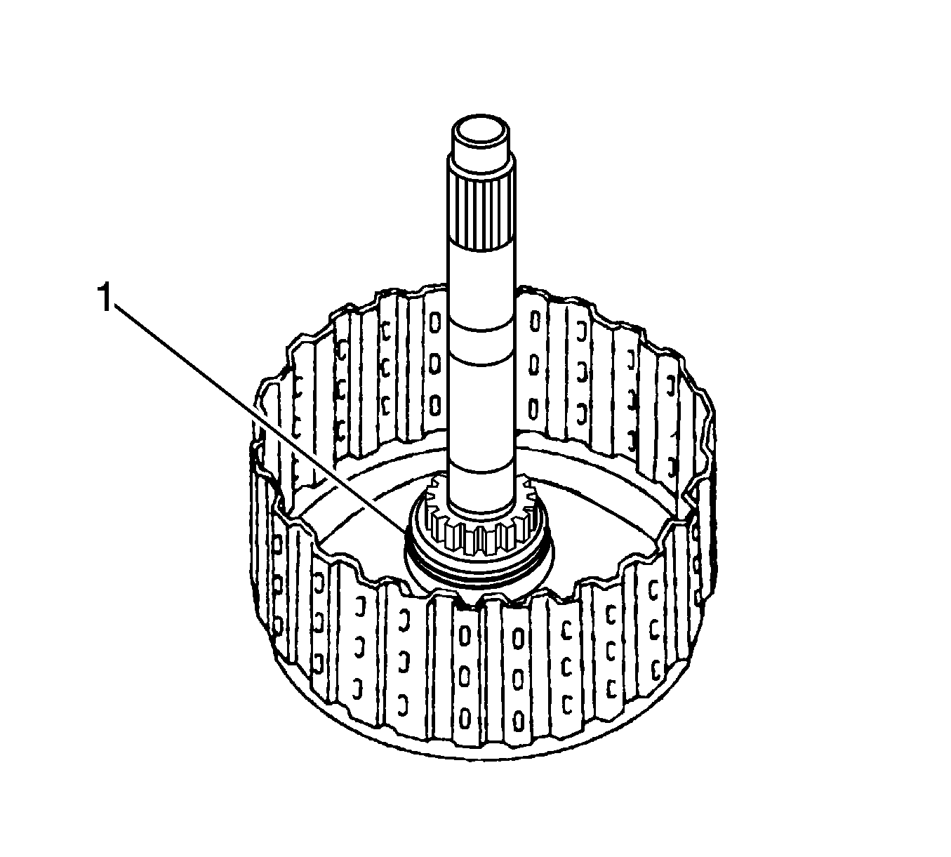
- Coat a new O-ring (1) with automatic transmission fluid (ATF) and install it to the intermediate shaft sub-assembly.
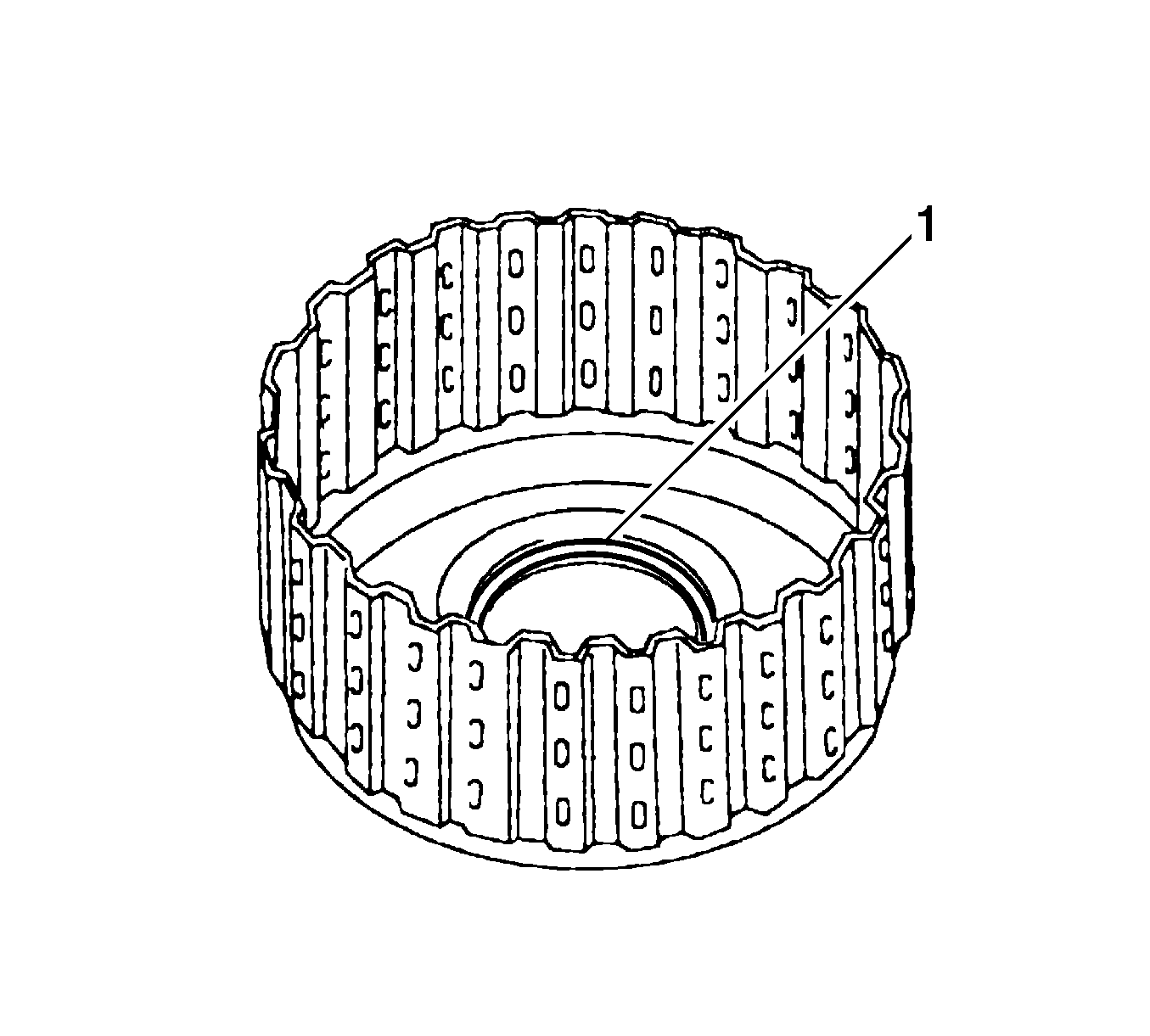
- Coat a new O-ring (1) with ATF, and install it to the forward clutch drum.

Note: Do not damage the O-ring and lip seal of forward clutch drum.
- Coat the forward clutch drum with ATF, install the forward clutch drum.

Note: Do not damage the lip seal of forward clutch return spring.
- Coat the forward clutch piston with ATF, install the forward clutch piston.
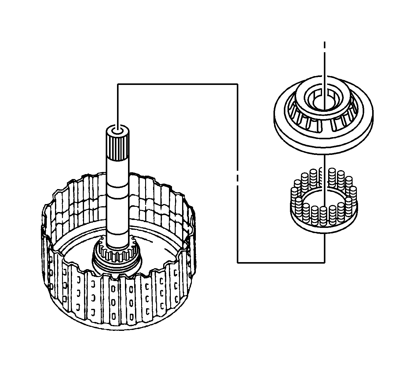
Note: Do not damage the lip seal of forward clutch return spring.
- Install the forward clutch return spring and clutch balancer.
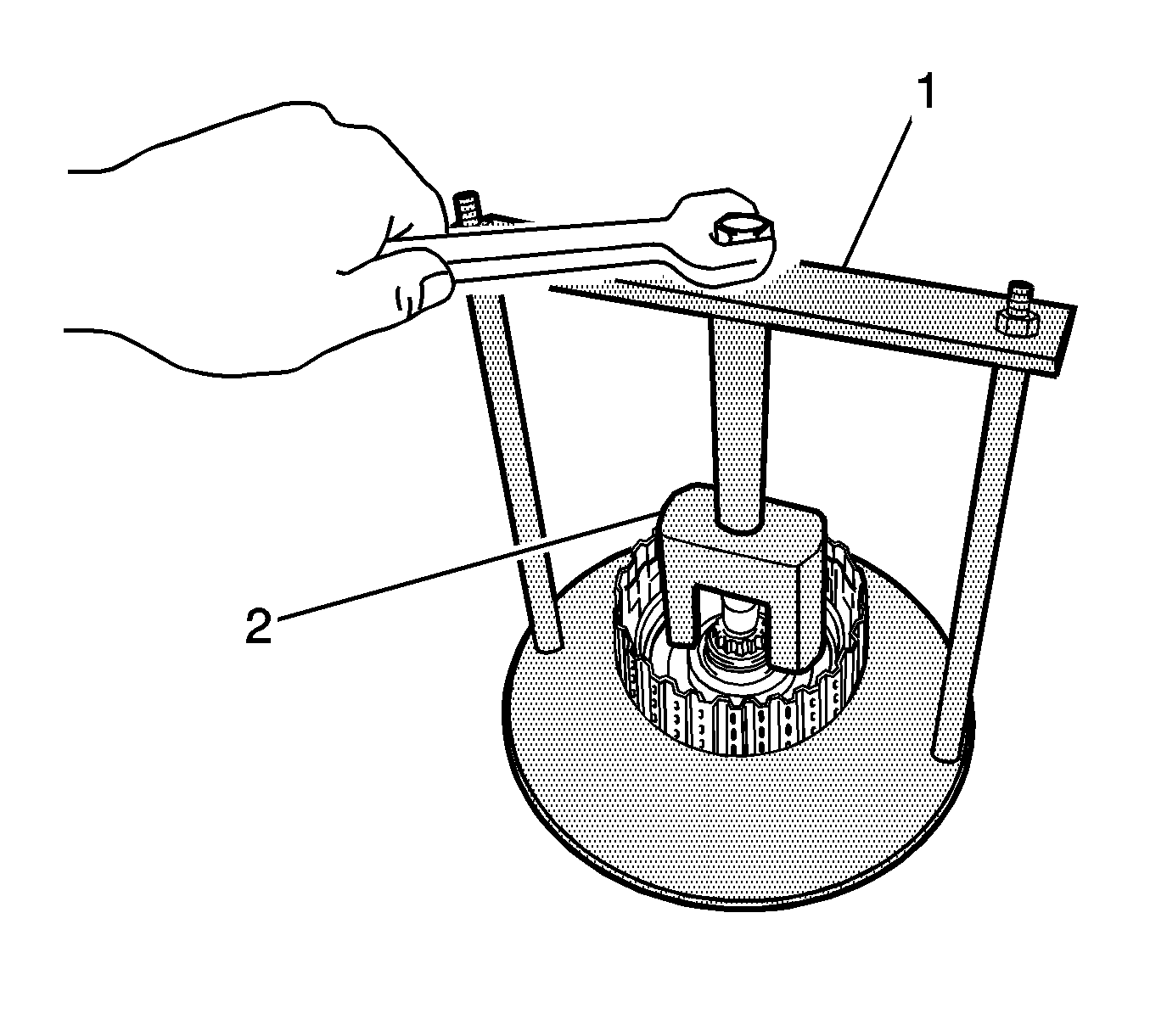
- Place
DT 46451
(1) and
DT 46452
(2)
on the clutch balancer and compress the piston return spring.
Note: Do not expand the snap ring excessively.
- Using a snap ring expander, install the snap ring.
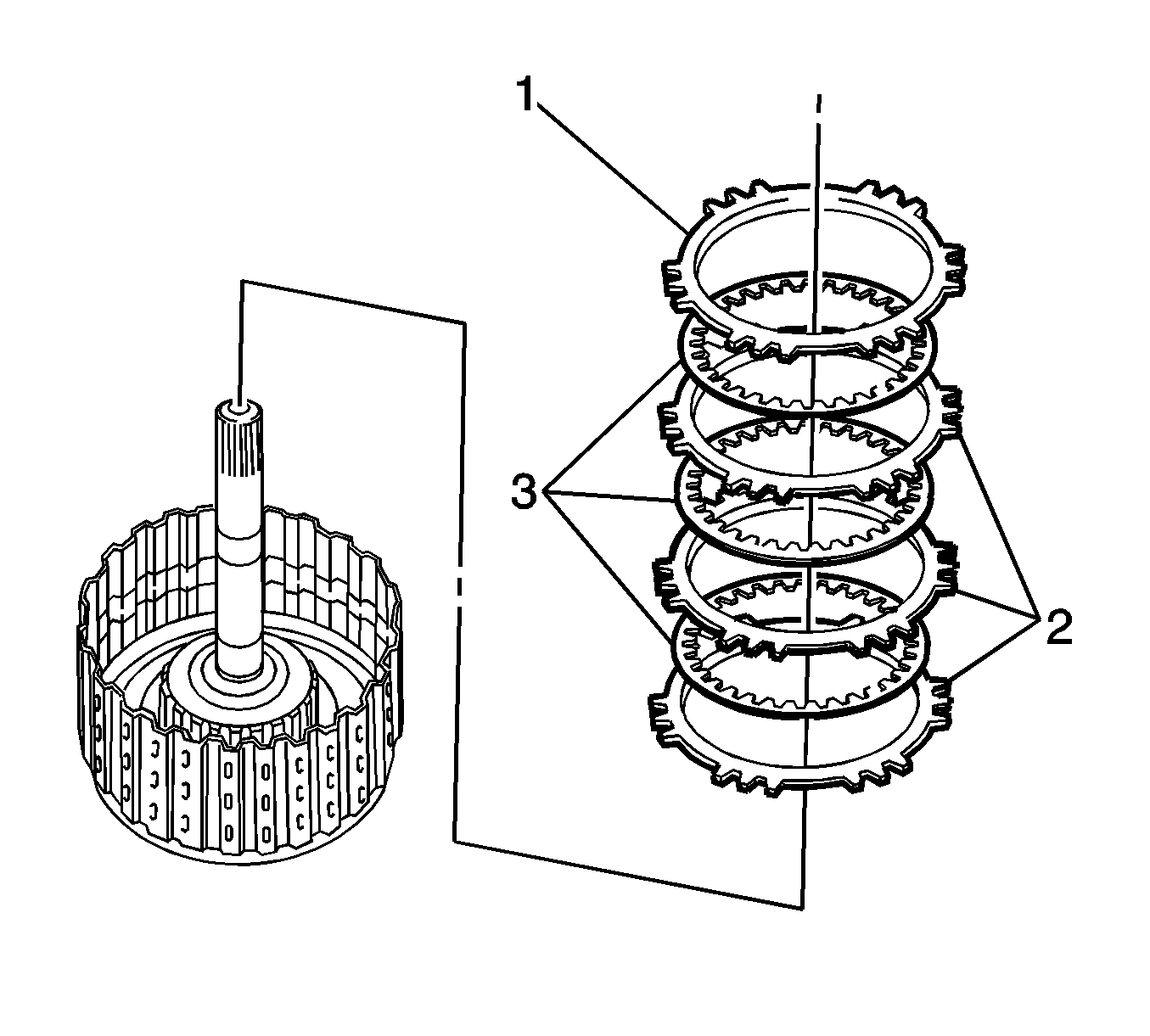
- Install the 3 plates (2), 3 discs (3), and the flange (1) in order 2-3-2-3-2-3-1.
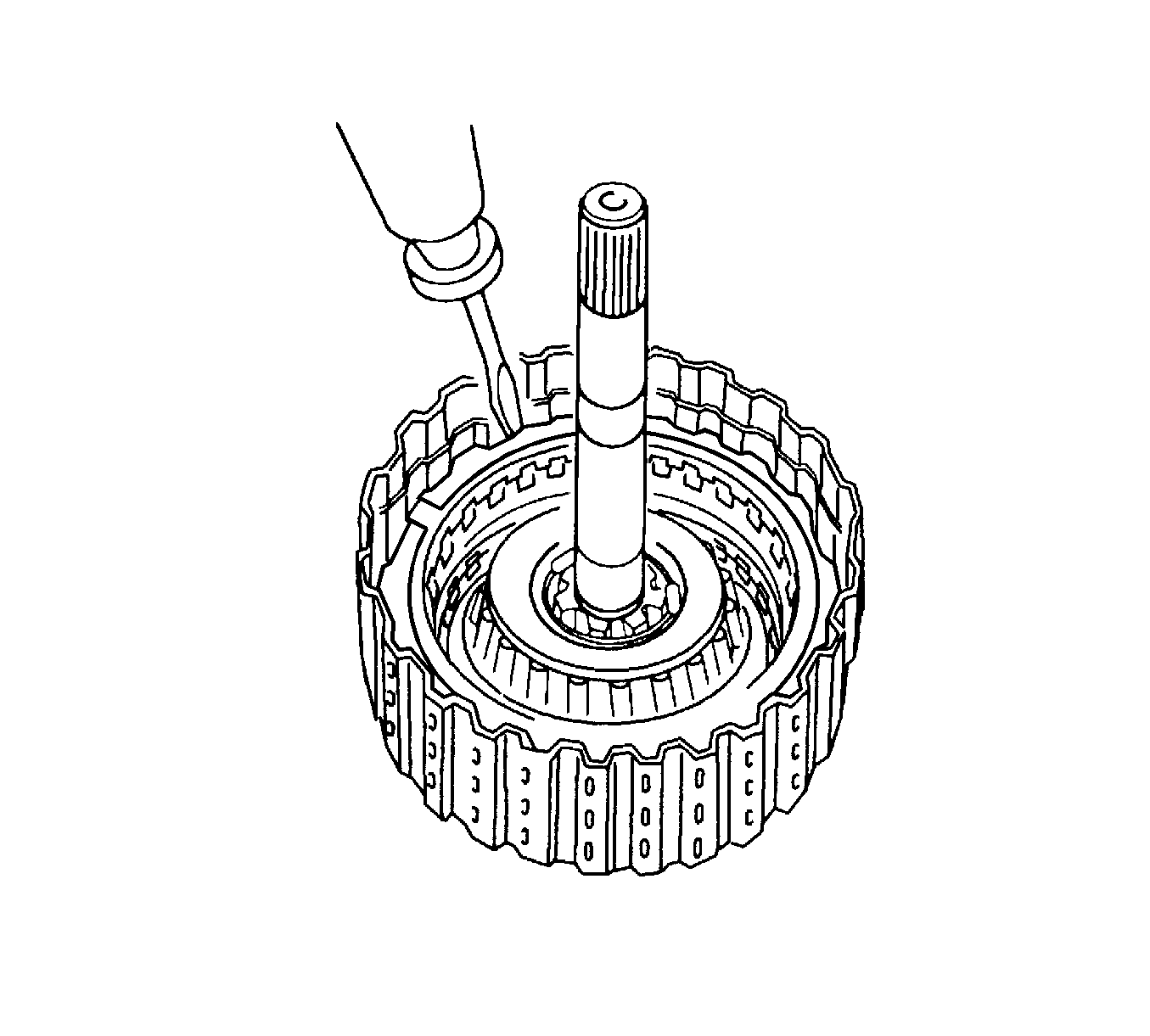
- Using a screwdriver, install the snap ring.
- Check that the end gap of the snap ring is not aligned with one of the cutouts.
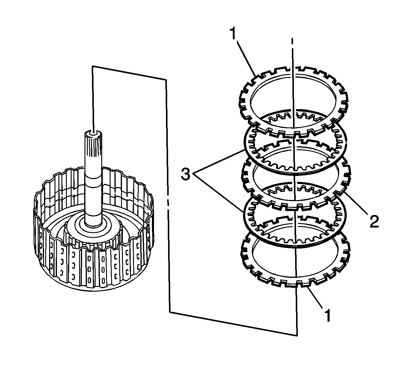
- Install the plate (2), 2 discs (3), and 2 flanges (1) in order 1-3-2-3-1.
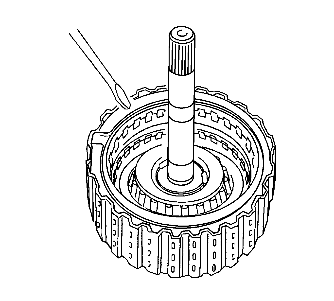
- Using a screwdriver, install the snap ring.
- Check that the end gap of the snap ring is not aligned with one of the cutouts.
Caution: Refer to Compressed Air Should Not Exceed 98 kPa (14 psi) Caution in the Preface section.
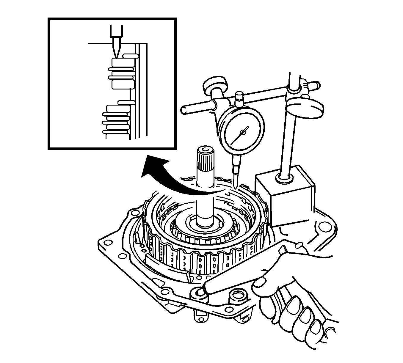
- Install the forward and reverse clutch and thrust needle roller bearing on the transaxle rear cover.
- Using a dial indicator, measure the reverse clutch pack clearance while applying and releasing compressed air.
| • | If the pack clearance is less than the limit of pack clearance, parts may have been assembled incorrectly, so check and reassemble again. |
| | If the pack clearance is non-standard, select another flange. |
Specifications
The pack clearance is 0.4-1 mm (0.0157-0.0394 in).
| • | There are 4 flanges in different thickness. |
Specifications
| • | The number 1 flange thickness is 3 mm (0.118 in).
|
| • | The number 2 flange thickness is 3.2 mm (0.126 in).
|
| • | The number 3 flange thickness is 3.4 mm (0.134 in).
|
| • | The number 4 flange thickness is 3.6 mm (0.142 in).
|
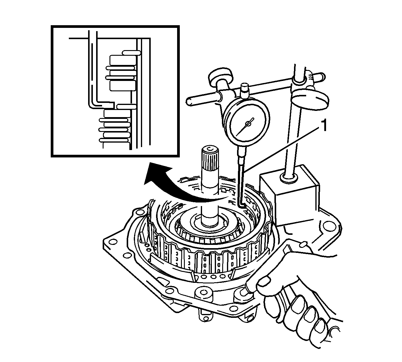
- Install the forward and reverse clutch and thrust needle roller bearing on the transaxle rear cover.
- Using a dial indicator and
DT 46464
(1) , measure the forward clutch pack clearance while applying and releasing compressed air.
| • | The forward and reverse clutch will come out as you apply the compressed air. Therefore, while the checking is being done, press on the input shaft of the forward and reverse clutch using stamping machine or alike so that the pressure is not applied
on the forward and reverse clutch. |
| • | If the pack clearance is less than the limit of pack clearance, parts may have been assembled incorrectly, so check and reassemble again. |
| | If the pack clearance is not within specifications, select another flange. |
Specifications
The pack clearance is 1.1-1.5 mm (0.043-0.059 in).
| • | There are 4 flanges in different thickness. |
Specifications
| • | The number 1 flange thickness is 3 mm (0.118 in).
|
| • | The number 2 flange thickness is 3.2 mm (0.126 in).
|
| • | The number 3 flange thickness is 3.4 mm (0.134 in).
|
| • | The number four flange thickness is 3.6 mm (0.142 in).
|


