For 1990-2009 cars only
Special Tools
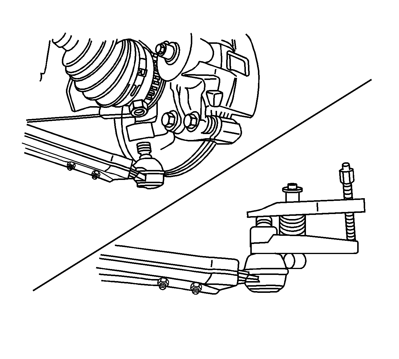
KM-507-C Ball Joint Remover
Removal Procedure
- Raise and support the vehicle. Refer to Lifting and Jacking the Vehicle.
- Place the jackstands under the frame of the vehicle.
- Lower the vehicle slightly so the weight of the vehicle rests on the frame and not on the control arms.
- If the transaxle blocks access to the control arm front mounting bolt, use a jack in order to slightly raise the transaxle case.
- Remove the front tire and wheel assembly. Refer to Tire and Wheel Removal and Installation.
- If equipped, disconnect the stabilizer shaft from the control arm by removing the control arm-link bolt assembly. Refer to Stabilizer Shaft Replacement.
- If equipped, remove the retaining clip from the ball joint stud.
- Remove the ball joint-to-knuckle nut from the ball joint stud.
- Push the top of the ball joint seal down.
- Position the bottom of the KM-507-C Ball Joint Remover between the ball joint seal and the knuckle.
- Disconnect the ball joint from the knuckle using the KM-507-C Remover .
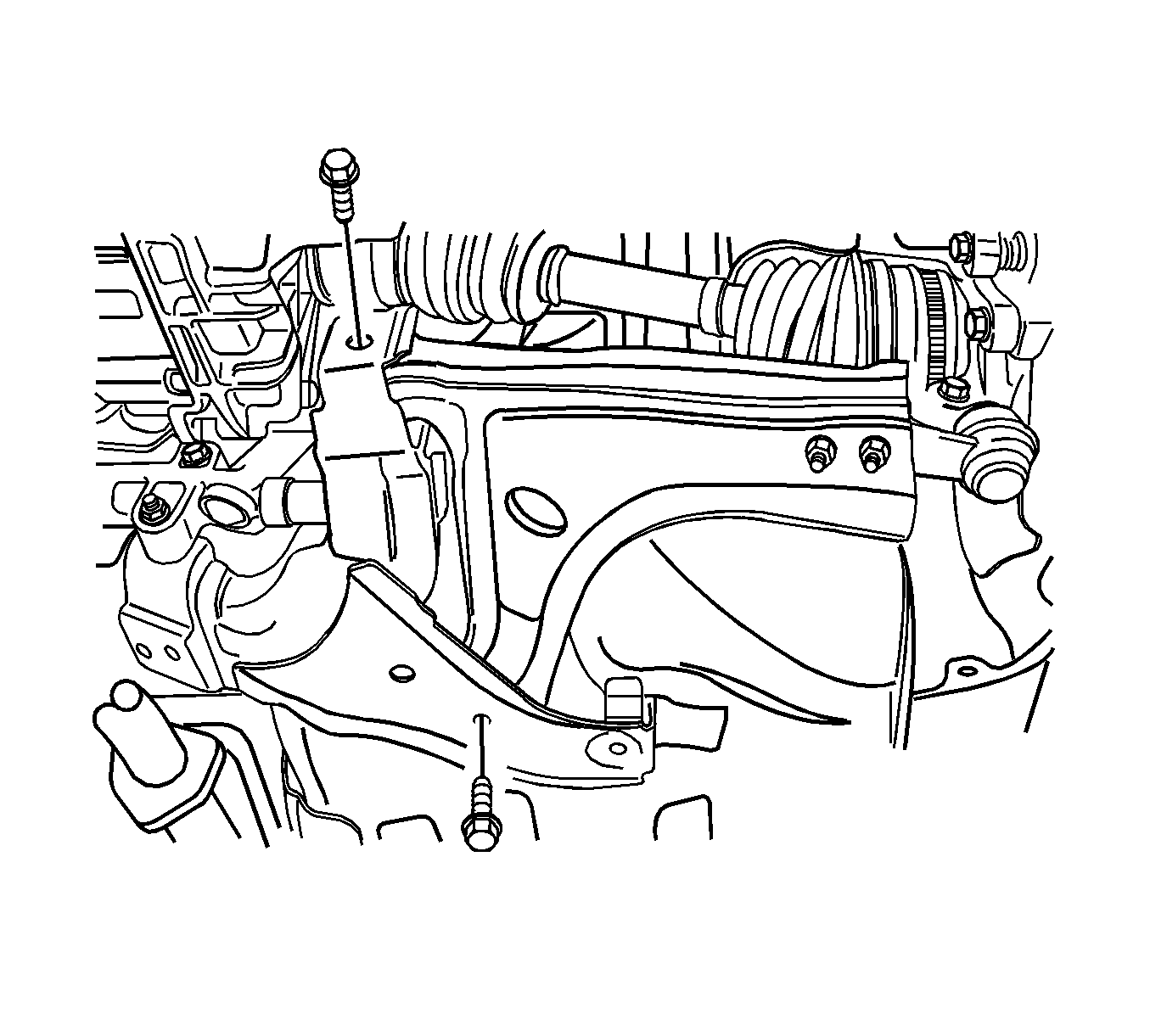
- Remove the control arm front mounting bolt and lock washer.
- Remove the control arm rear mounting bolt.
- Remove the control arm from the vehicle.


Installation Procedure
- Install the control arm onto the vehicle.
- Install the control arm front mounting bolt and lock washer.
- Apply a thread sealer to the control arm rear mounting bolt.
- Install the control arm rear mounting bolt.
- If equipped, install the stabilizer shaft link bolt assembly to the control arm. Refer to Stabilizer Shaft Replacement.
- Install the ball joint to the steering knuckle with the nut and tighten to 55 N·m (41 lb ft).
- If equipped, install the retaining clip to the ball joint stud.
- Install the front tire and wheel assembly. Refer to Tire and Wheel Removal and Installation.
- Place the jackstands under the control arms.
- Lower the vehicle onto the jackstands.
- Tighten the control arm rear mounting bolts to 110 N·m (81 lb ft).
- Tighten the control arm front mounting bolt to 110 N·m (81 lb ft).
- Remove the jackstands.
- Lower the vehicle.

Note: Do not tighten the control arm bolts at this point.
Caution: Refer to Fastener Caution in the Preface section.
Caution: Use a new self-locking nut when installing the control arm link assembly. Failure to do so may allow the normal road and vehicle vibration to possibly loosen the nut and could cause vehicle handling concerns.
Note: The control arms must support the weight of the vehicle while the control arm mounting bolts are being tightened.
