For 1990-2009 cars only
Removal Procedure
- LOCK the steering column and verify the front wheels are in the straight ahead position.
- Disconnect the negative battery cable. Refer to Battery Negative Cable Disconnection and Connection.
- Disable the supplemental inflatable restraint (SIR) system. Refer to SIR Disabling and Enabling.
- Remove the instrument panel lower trim panel. Refer to Instrument Panel Lower Trim Panel Replacement.
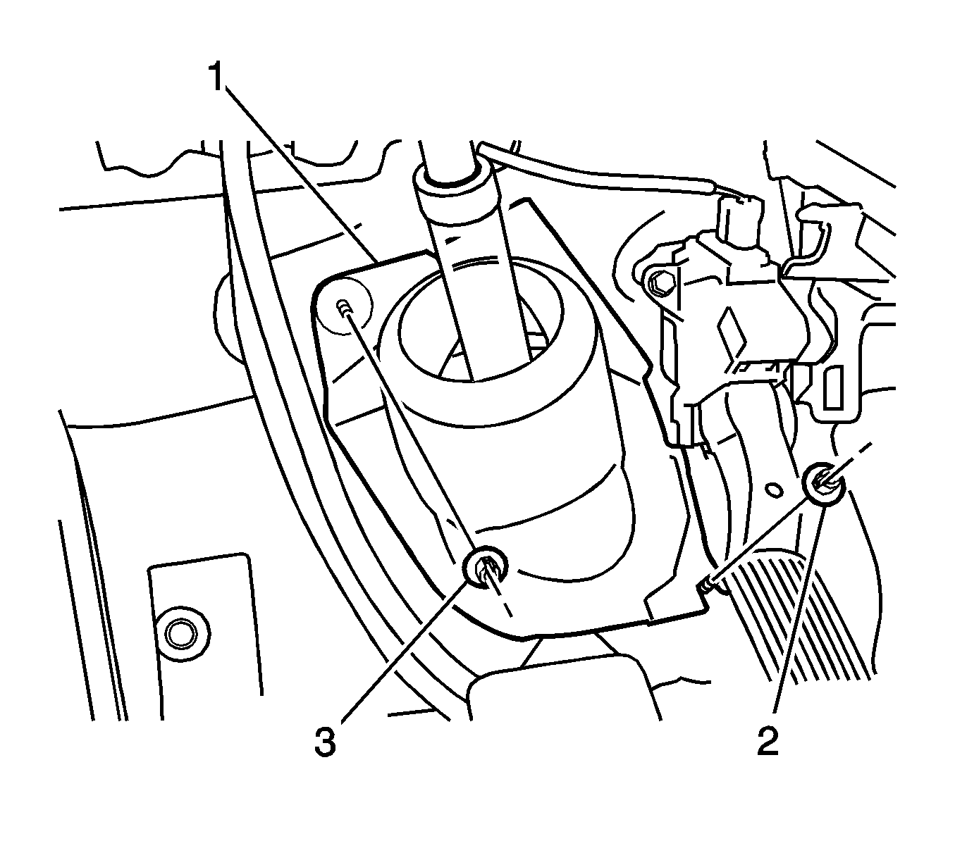
- Turn back the floor carpet and remove the 2 clips (2, 3) and the column hole cover silencer sheet (1).
- If the vehicle has front-wheel drive, complete the following steps:
- If the vehicle has all-wheel drive, complete the following steps:
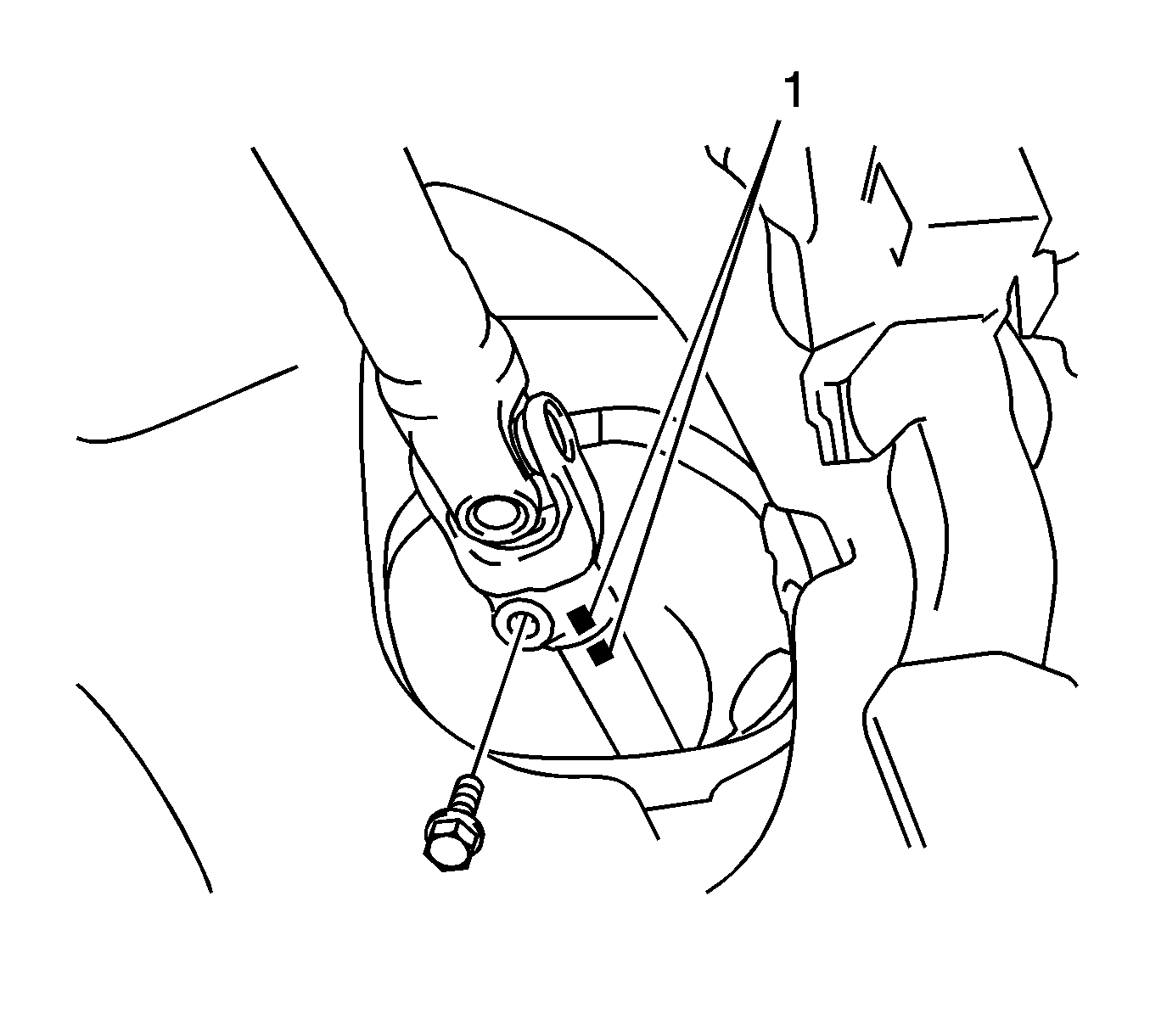
- Remove the bolt (1) and the intermediate shaft from the steering column shaft.
Caution: Refer to Steering Column in Lock Position Caution in the Preface section.
Note: The front-wheel drive models have an intermediate steering shaft and a lower intermediate steering shaft. The all-wheel drive model has an intermediate steering shaft, but does not have a lower intermediate steering shaft.


| 6.1. | Put match marks (1) on the intermediate shaft and on the lower intermediate shaft. |
| 6.2. | Remove the bolt. |
| 6.3. | Separate the intermediate shaft from the lower intermediate shaft. |
| 7.1. | Put match marks on the intermediate shaft and on the steering gear pinion shaft. |
| 7.2. | Remove the bolt. |
| 7.3. | Separate the intermediate shaft from the steering gear pinion shaft. |

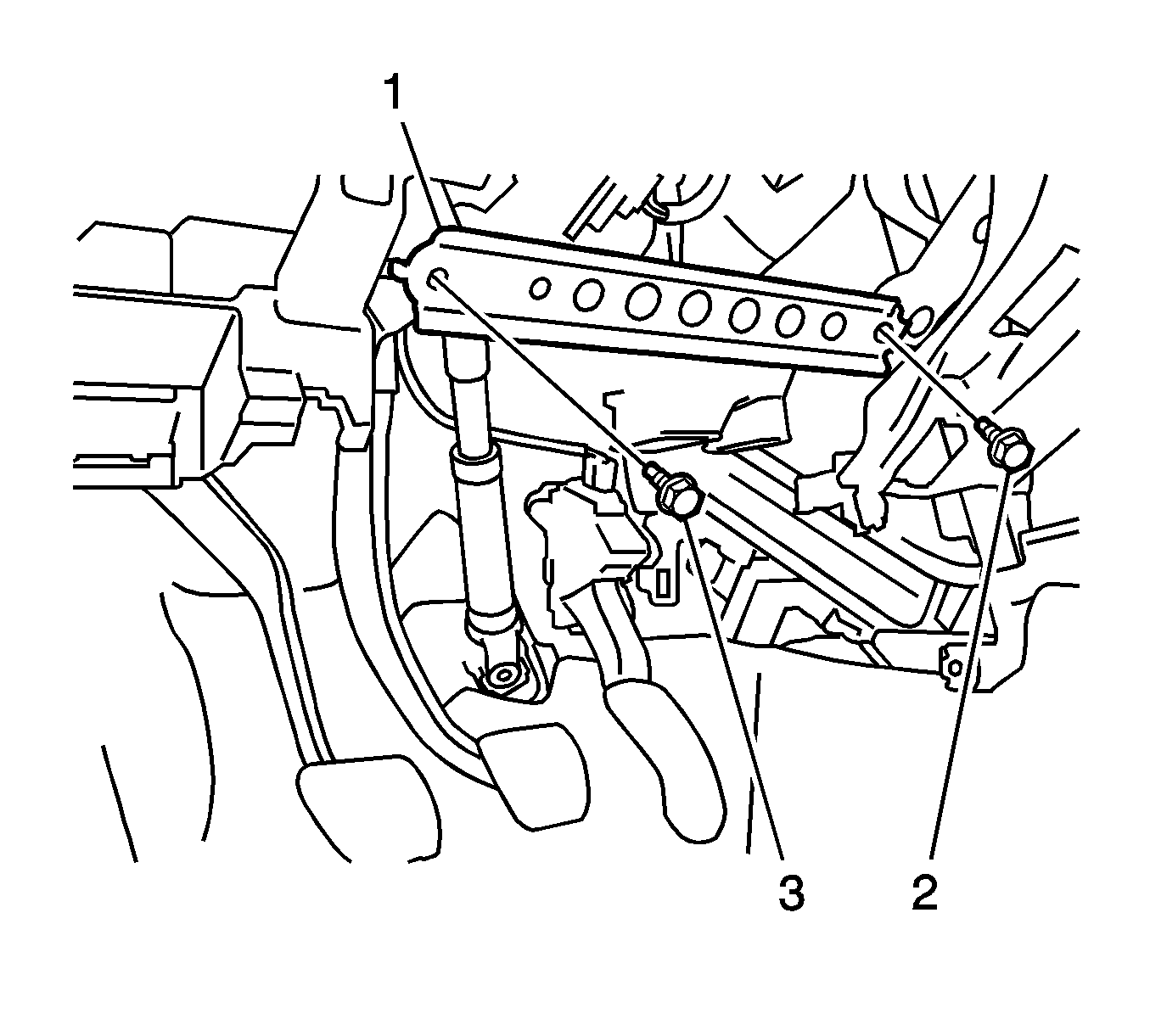
| 7.4. | Remove the 2 bolts (2, 3) and the instrument panel sub reinforcement (1). |

| 7.5. | Put match marks (1) on the intermediate shaft and on the steering column assembly. |
| 7.6. | Loosen the steering column bolt and the 2 nuts as much as necessary in order to separate the intermediate shaft from the steering column shaft. |

Installation Procedure
- Align the match marks (1) on the intermediate shaft and on the steering column assembly.
- Install the intermediate shaft and the bolt (1) to the steering column shaft. Tighten the bolt to 35 N·m (26 lb ft).
- Tighten the steering column bolt and the 2 nuts to 25 N·m (18 lb ft).
- Ensure the front wheels are in the straight ahead position.
- If the vehicle has front-wheel drive, align the match marks (1) on the intermediate shaft and on the lower intermediate shaft.
- If the vehicle has all-wheel drive, align the match marks on the intermediate shaft and on the power steering gear pinion shaft.
- Install the bolt. Tighten the bolt to 35 N·m (26 lb ft).
- Install the instrument panel sub reinforcement (1) with the 2 bolts (2, 3). Tighten the bolts to 24 N·m (18 lb ft).
- Install the column hole cover silencer sheet (1) with the 2 clips (2, 3).
- Install the floor carpet.
- Install the instrument panel lower trim panel. Refer to Instrument Panel Lower Trim Panel Replacement.
- Connect the negative battery cable. Refer to Battery Negative Cable Disconnection and Connection.
- Enable the SIR system. Refer to SIR Disabling and Enabling.
- Calibrate the torque sensor zero point. Refer to Steering Angle Sensor Initialization and Steering Shaft Torque Sensor Zero Point Calibration.

Caution: Refer to Fastener Caution in the Preface section.


