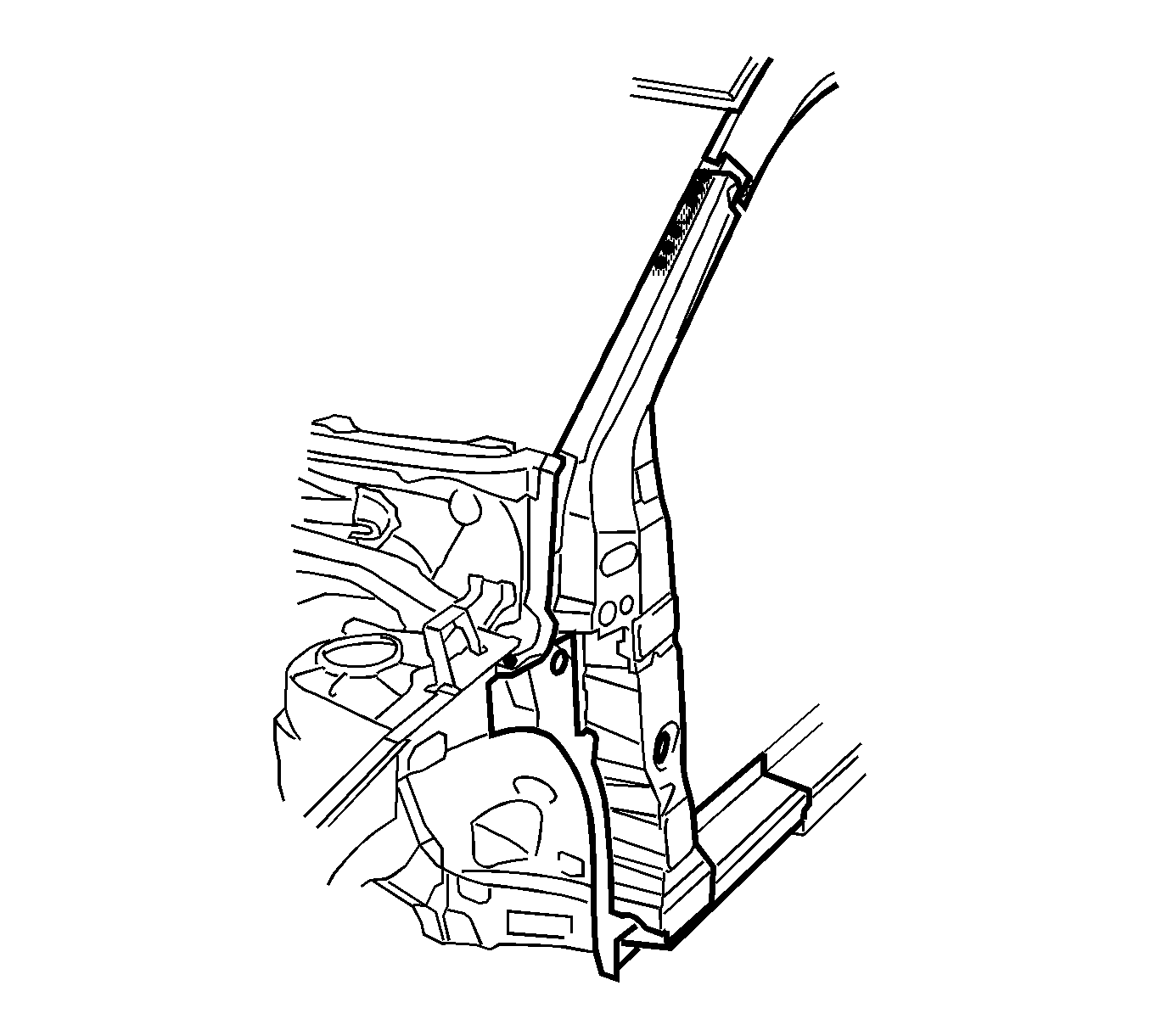
For 1990-2009 cars only
Removal Procedure
Warning: Refer to Approved Equipment for Collision Repair Warning in the Preface section.
Note: When replacing panels that involve servicing of stationary glass, refer to Adhesive Installation of Stationary Windows before performing any priming or refinishing.
- Disable the SIR system. Refer to SIR Disabling and Enabling.
- Disconnect the negative battery cable.
- Remove all related panels and components.
- Repair as much of the damage as possible to factory specifications. Refer to Dimensions - Body.
- Note the location and remove the sealers and anti-corrosion materials from the repair area, as necessary. Refer to Anti-Corrosion Treatment and Repair.
- Perform the necessary procedures to gain access to repair. Refer to Upper Rail Replacement.
- Position all wiring out of the way to prevent damage and for best access to vehicle.
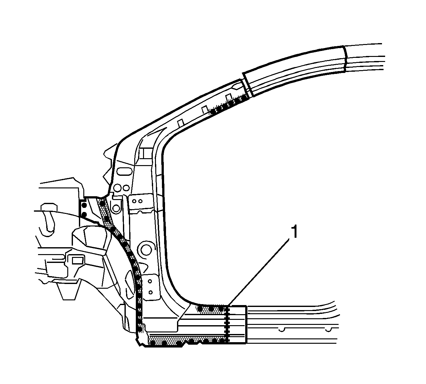
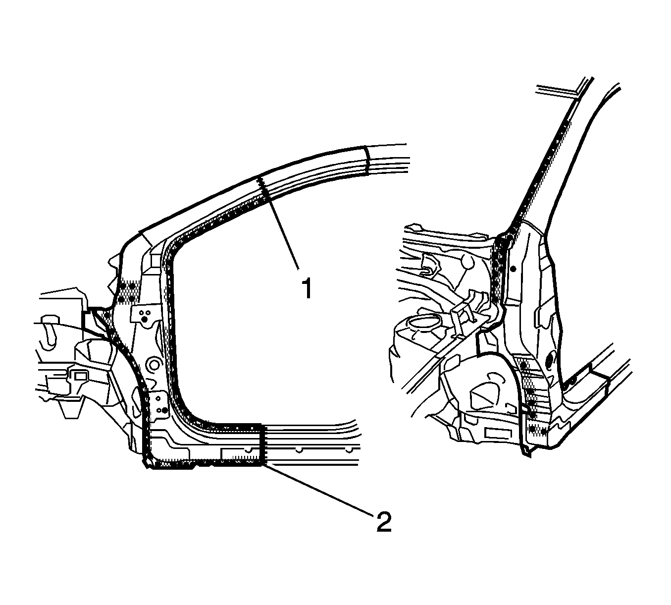
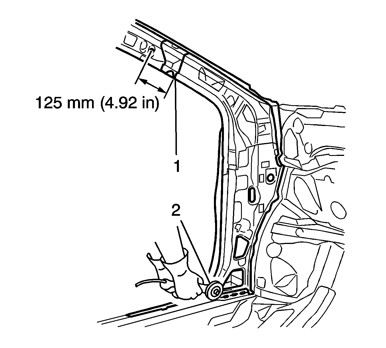
- Select a cutting point (1) on the hinge pillar approximately 130 mm (5.12 in) from the bottom of the windshield flange.
- At the selected point, cut through the outer panel, leaving the inner panel intact.
- Cut through the rocker panel section of the door opening frame assembly. The cut point (2) should be referenced with the service part.
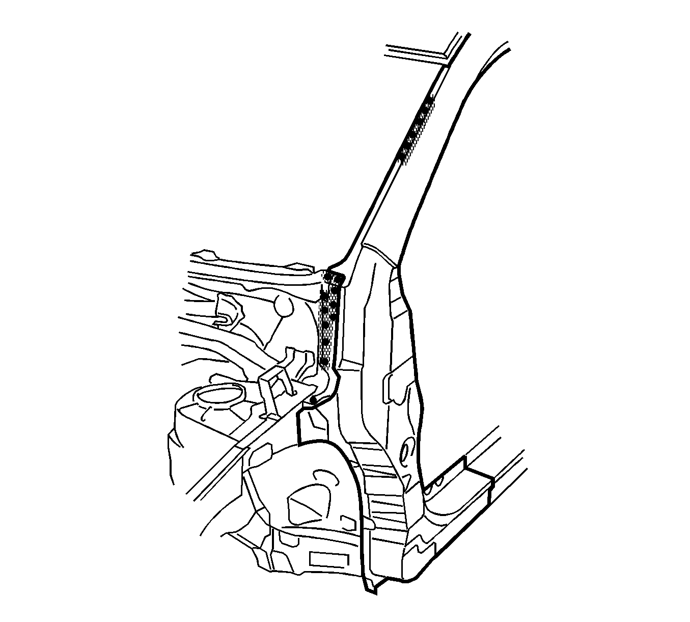
- Locate and drill out all factory welds. Note the number and location of welds for installation of the front hinge pillar.
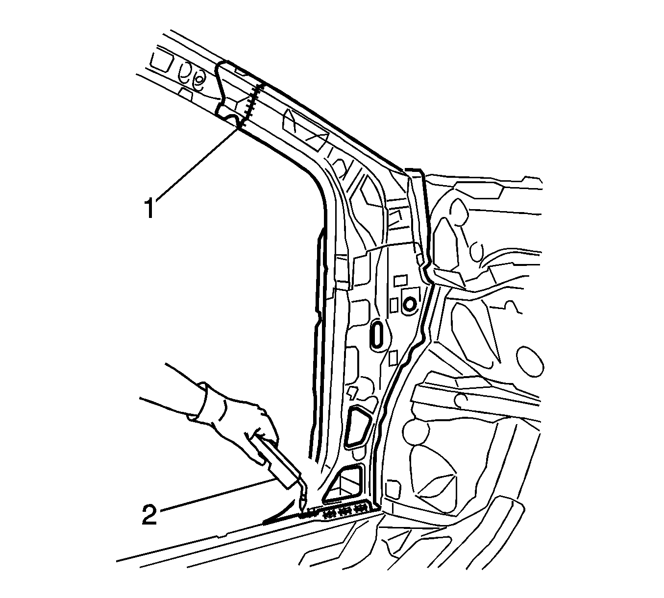
- Make a cut to the upper pillar as shown (1).
- Make a cut to the lower part of the pillar as shown (2).
- Drill out all remaining factory welds as necessary.
- Remove the damaged section of the outer hinge pillar.
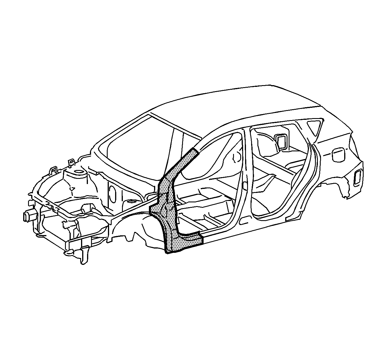
Warning: Refer to Foam Sound Deadeners Warning in the Preface section.
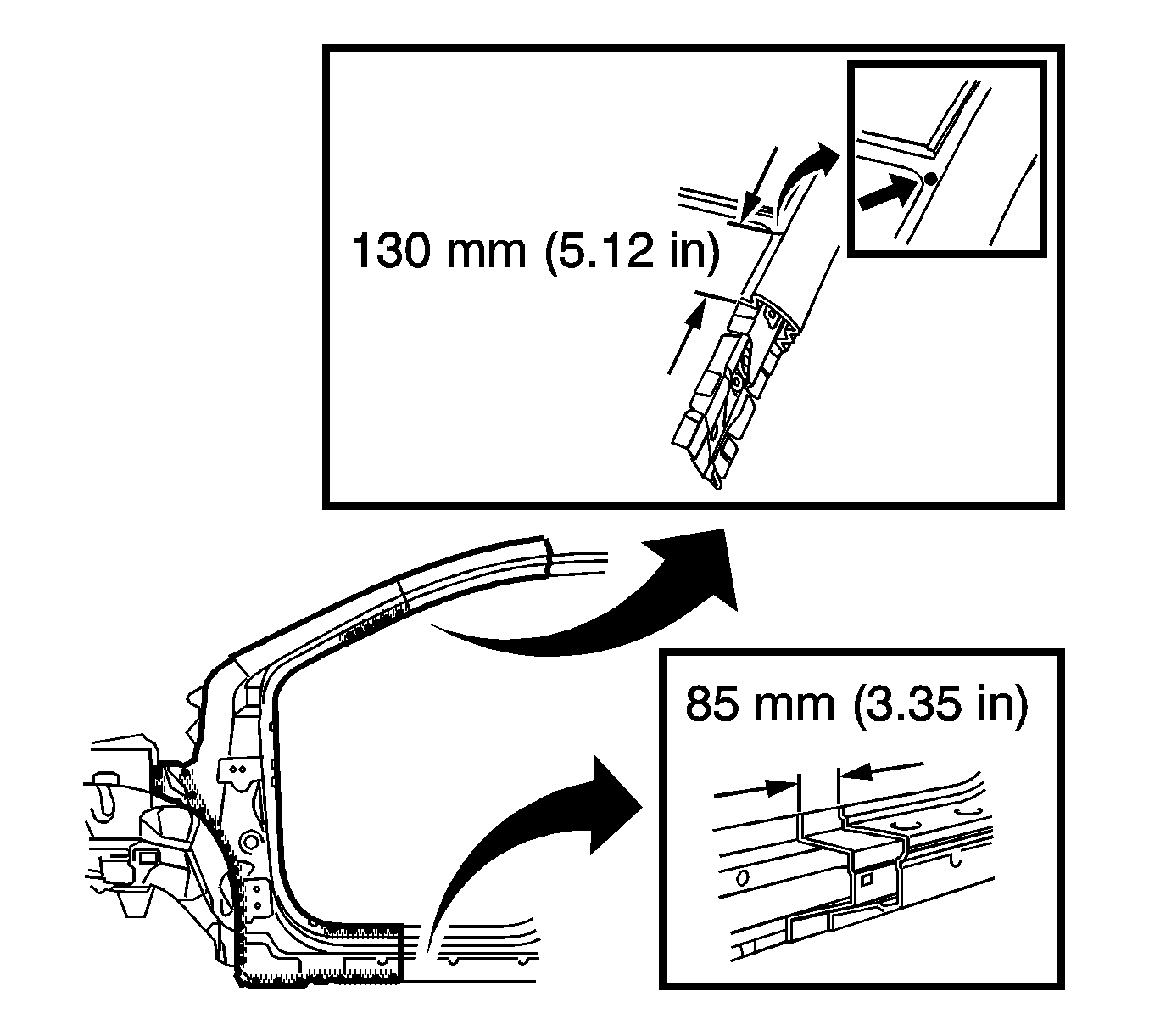
Note: Note the location of the sound deadening foam for installation.
Installation Procedure
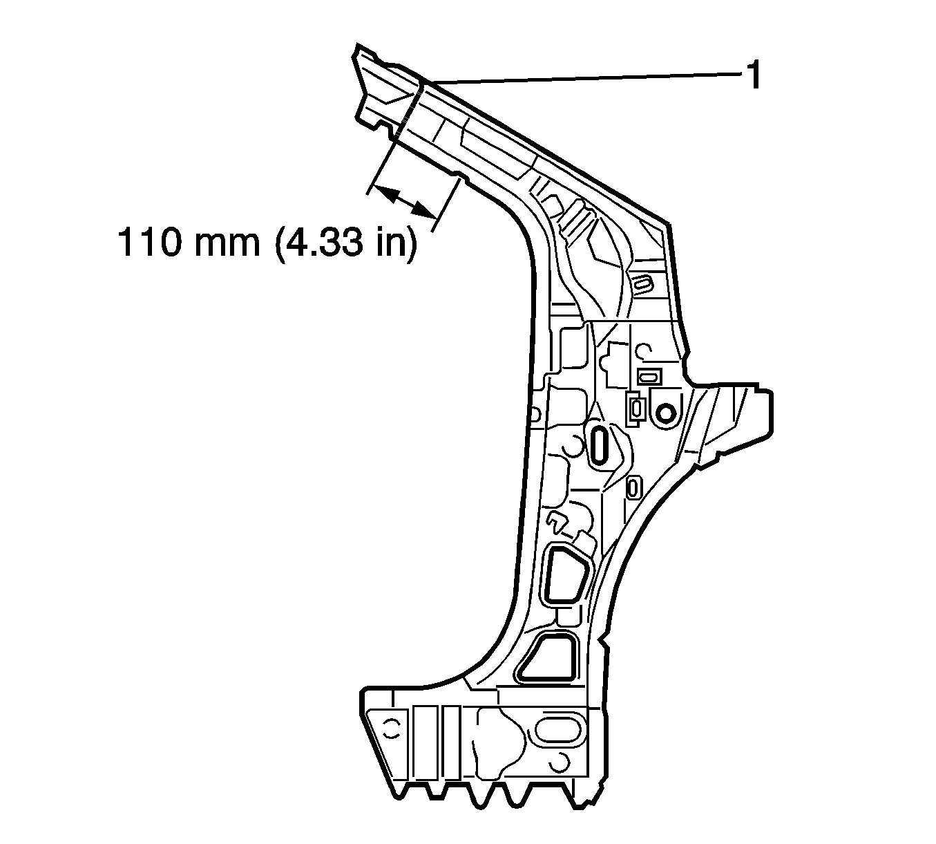
- On the service part, make a cut (1) 110 mm (4.33 in) from the marks as shown.
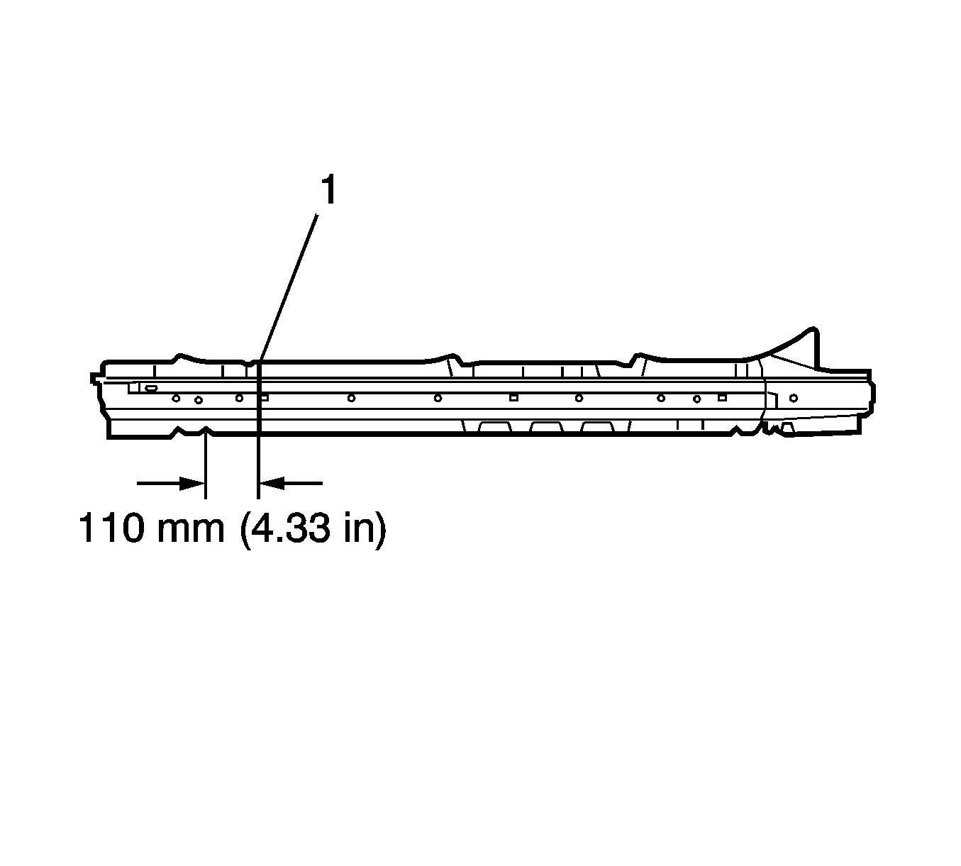
- Remove a section of inner rocker panel (1). Cut 1.10 mm (4.33 in) from the area as shown.
- Drill 8 mm (5/16 in) plug weld holes as necessary in locations noted from the original panel.
- Prepare all mating surfaces as necessary.
- Apply 3M® Weld-Thru coating P/N 05916 or equivalent to all mating surfaces
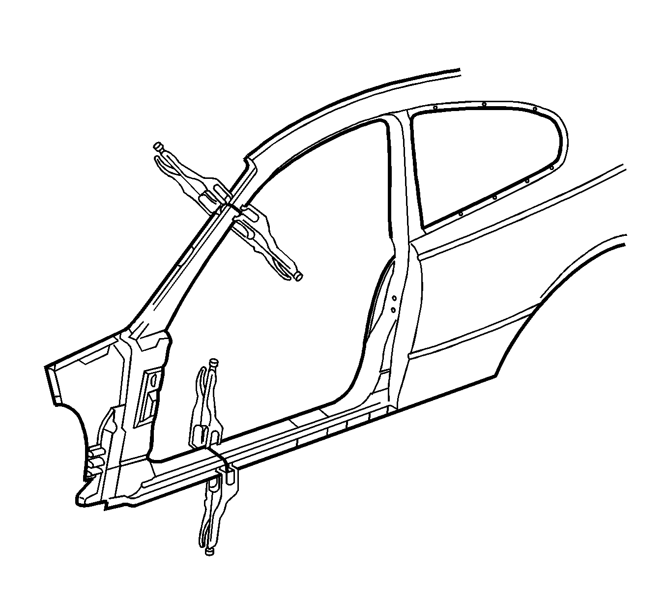
- Clamp the replacement panel in position on the vehicle and check the door opening dimensions. Refer to Dimensions - Body.
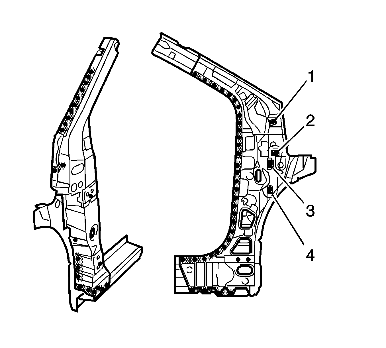
- Tack weld the inner pillar upper areas (1), (2),(3) and (4) accordingly.
- Plug weld accordingly.
- Stitch weld along the rocker panel reinforcement (1).
- Make 25 mm (1 in) welds along the seams with 25 mm (1 in) gaps between.
- Go back and complete the stitch weld to create a solid weld joint with minimal heat distortion.
- Plug weld accordingly.
- Stitch weld along the upper inner pillar (1) and lower pillar (2).
- Make 25 mm (1 in) welds along the seams with 25 mm (1 in) gaps between.
- Go back and complete the stitch weld to create a solid weld joint with minimal heat distortion.
- Plug weld the upper and middle area accordingly.
- Stitch weld along the upper outer pillar (1) and lower pillar (2).
- Make 25 mm (1 in) welds along the seams with 25 mm (1 in) gaps between.
- Go back and complete the stitch weld to create a solid weld joint with minimal heat distortion.
- Complete the remaining plug welds.
- Complete the necessary procedures. Refer to Upper Rail Replacement.
- Clean and prepare all welded surfaces.
- Apply the sealers and anti-corrosion materials to the repair area, as necessary. Refer to Anti-Corrosion Treatment and Repair.
- Paint the repair area. Refer to Basecoat/Clearcoat Paint Systems.
- Install all related panels and components.
- Connect the negative battery cable.
- Enable the SIR system. Refer to SIR Disabling and Enabling.
Note: If the location of the original plug weld holes can not be determined, or if structural weld-thru adhesive is present, space the plug weld holes every 40 mm (1½ in) apart.
