For 1990-2009 cars only
Removal Procedure
Warning: Refer to Approved Equipment for Collision Repair Warning in the Preface section.
- Disable the SIR system. Refer to SIR Disabling and Enabling.
- Disconnect the negative battery cable.
- Remove the sealers and anti-corrosion materials from the repair area, as necessary. Refer to Anti-Corrosion Treatment and Repair.
- Remove the left upper tie bar, if necessary. Refer to Tie Bar Replacement - Left Side.
- Remove the right upper tie bar, if necessary. Refer to Tie Bar Replacement - Right Side.
- Remove the upper rail. Refer to Upper Rail Replacement.
- Repair as much of the damage as possible.
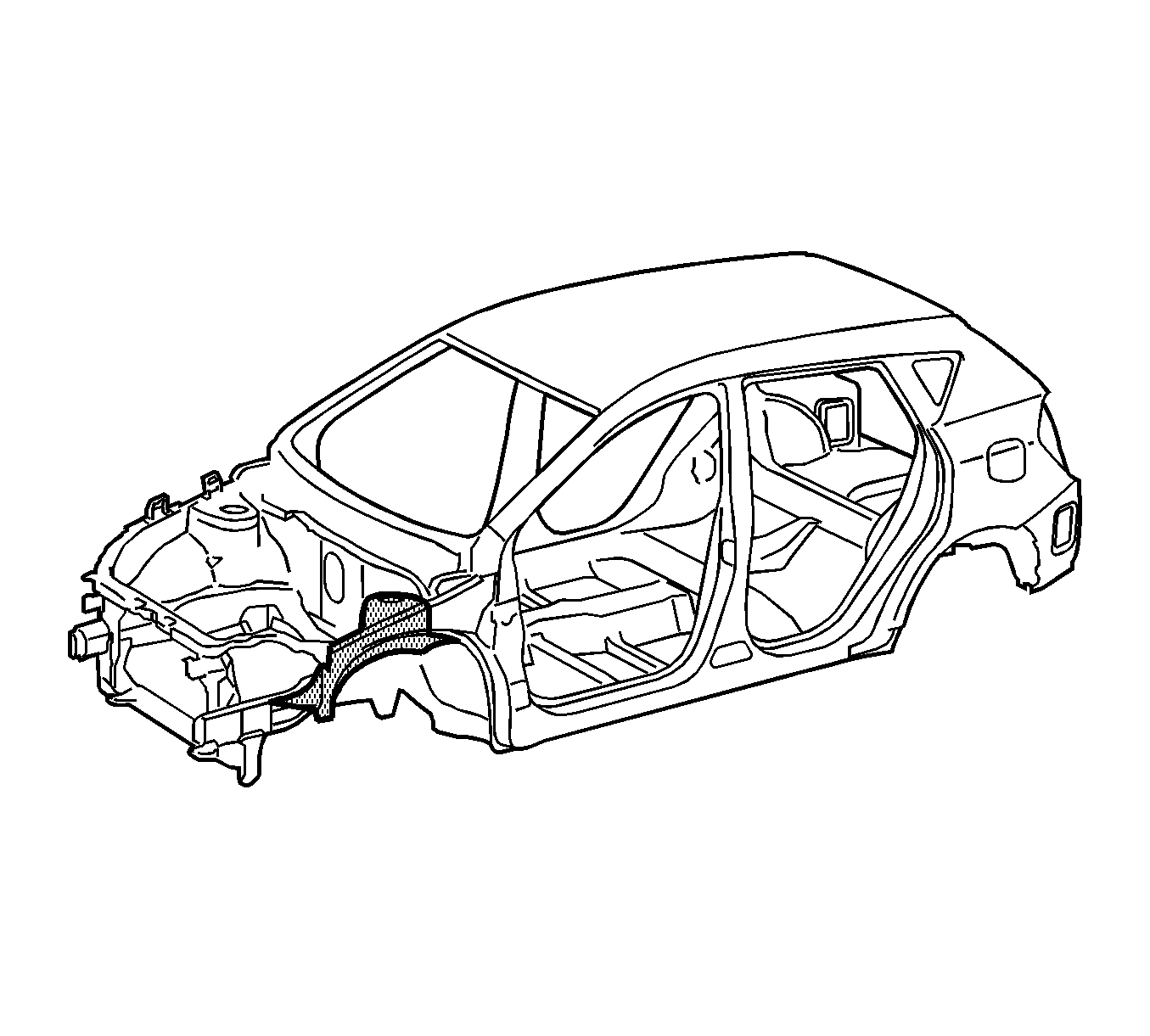
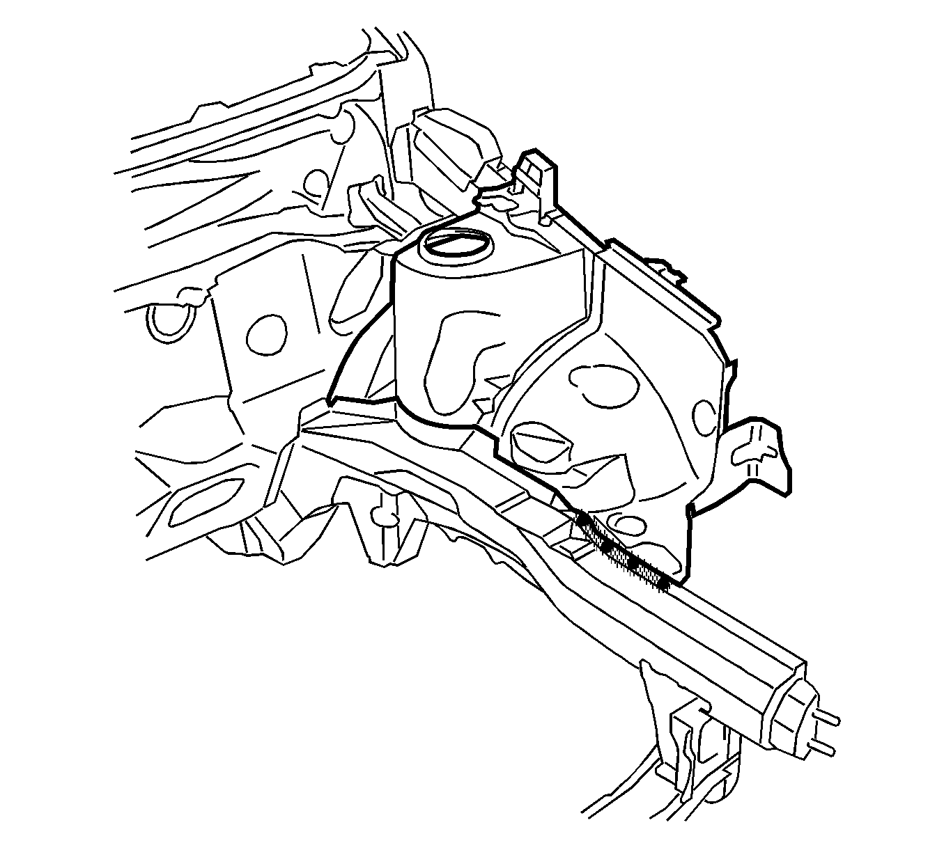
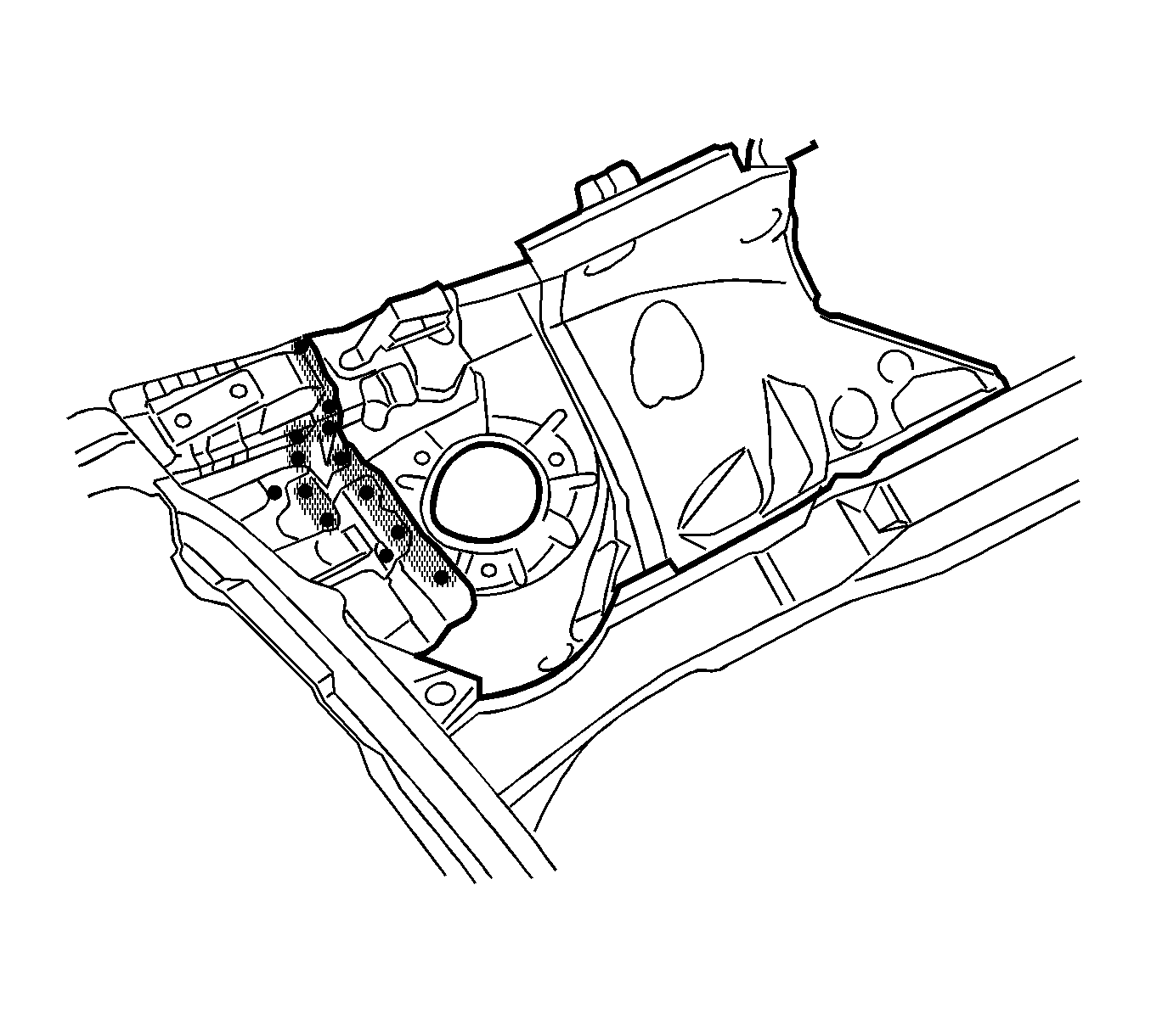
- Locate, mark, and drill out all factory welds attaching the front wheelhouse panel to the lower frame rail. Note the number and location of welds for installation of the service assembly.
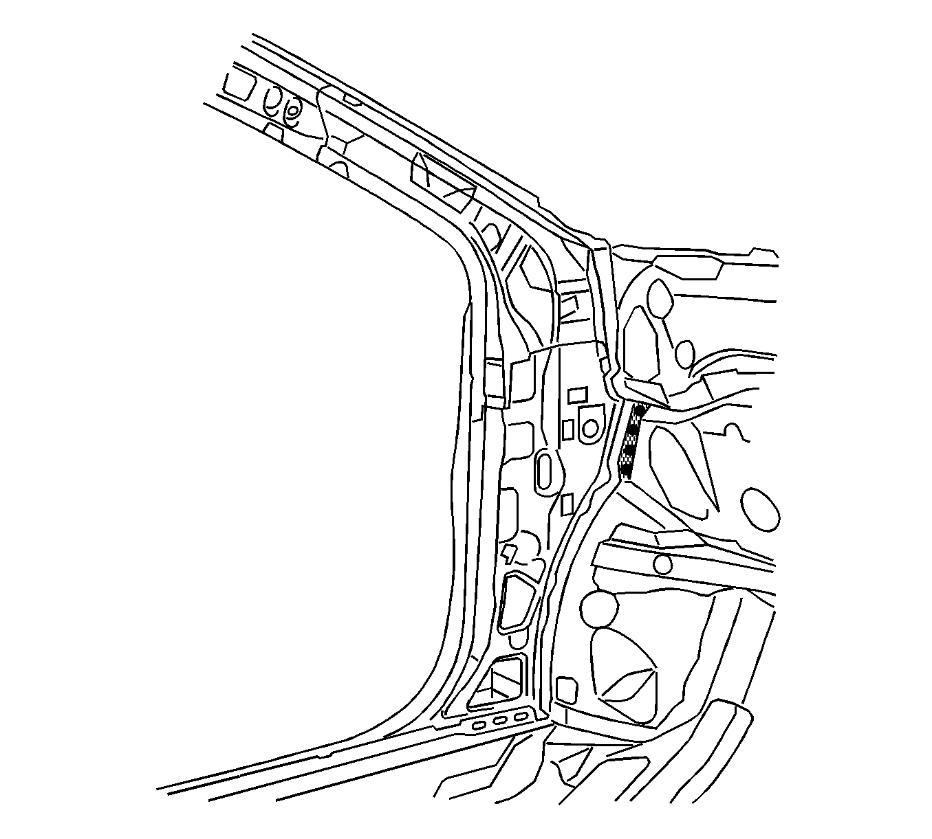
- Locate, mark, and drill out all factory welds attaching the wheelhouse panel to the cowl panel.
- Locate, mark and drill out all factory welds attaching the wheelhouse panel to the front lower and upper rail.
- Locate, mark and drill out all factory welds attaching the wheelhouse panel to the upper cowl panel.
- Remove the wheelhouse from the vehicle.
Note: . The front wheelhouse service panel is serviced as a complete assembly, which includes the upper front strut mounting surface. The upper strut mounting surface is a dimensionally critical area. Use dimensional measuring equipment to locate the front wheelhouse assembly.
Note: Inspect the front of the cowl for damage. If the metal surface is damaged, the cowl panel must be repaired to restore the structural integrity of the vehicle.
Installation Procedure
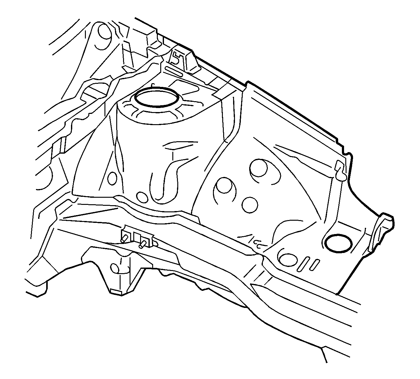
- Prepare the mating surfaces as necessary.
- Apply 3M Weld-Thru Coating P/N 05913 or equivalent to all mating surfaces.
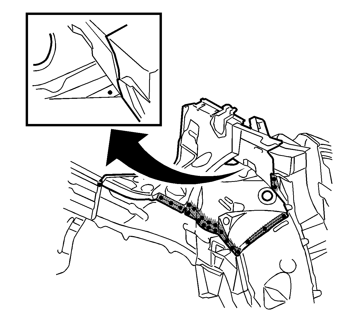
- Drill 8-mm (5/16-in) plug weld holes, as necessary, in the locations noted from the original assembly.
- Position the wheelhouse on the vehicle. Check for proper fit using 3-dimensional measuring equipment.
- When the service assembly is correctly positioned, plug weld accordingly.
- Install the upper rail. Refer to Upper Rail Replacement.
- Install the left upper tie bar, if removed. Refer to Tie Bar Replacement - Left Side.
- Install the right upper tie bar, if removed. Refer to Tie Bar Replacement - Right Side.
- Measure frequently to ensure proper fit and alignment.
- Clean and prepare all welded surfaces.
- Apply the sealers and anti-corrosion materials to the repair area, as necessary. Refer to Anti-Corrosion Treatment and Repair.
- Paint the repaired area. Refer to Basecoat/Clearcoat Paint Systems.
- Install all related panels and components.
- Connect the negative battery cable.
- Enable the SIR system. Refer to SIR Disabling and Enabling.
Note: If the location of the original plug weld holes can not be determined, or if structural weld-thru adhesive is present, space the plug weld holes every 40 mm (1½ in).
