For 1990-2009 cars only
Removal Procedure
- Disconnect the negative battery cable from the battery. Refer to Battery Negative Cable Disconnection and Connection.
- Remove the battery. Refer to Battery Replacement.
- Remove the battery tray. Refer to Battery Tray Replacement.
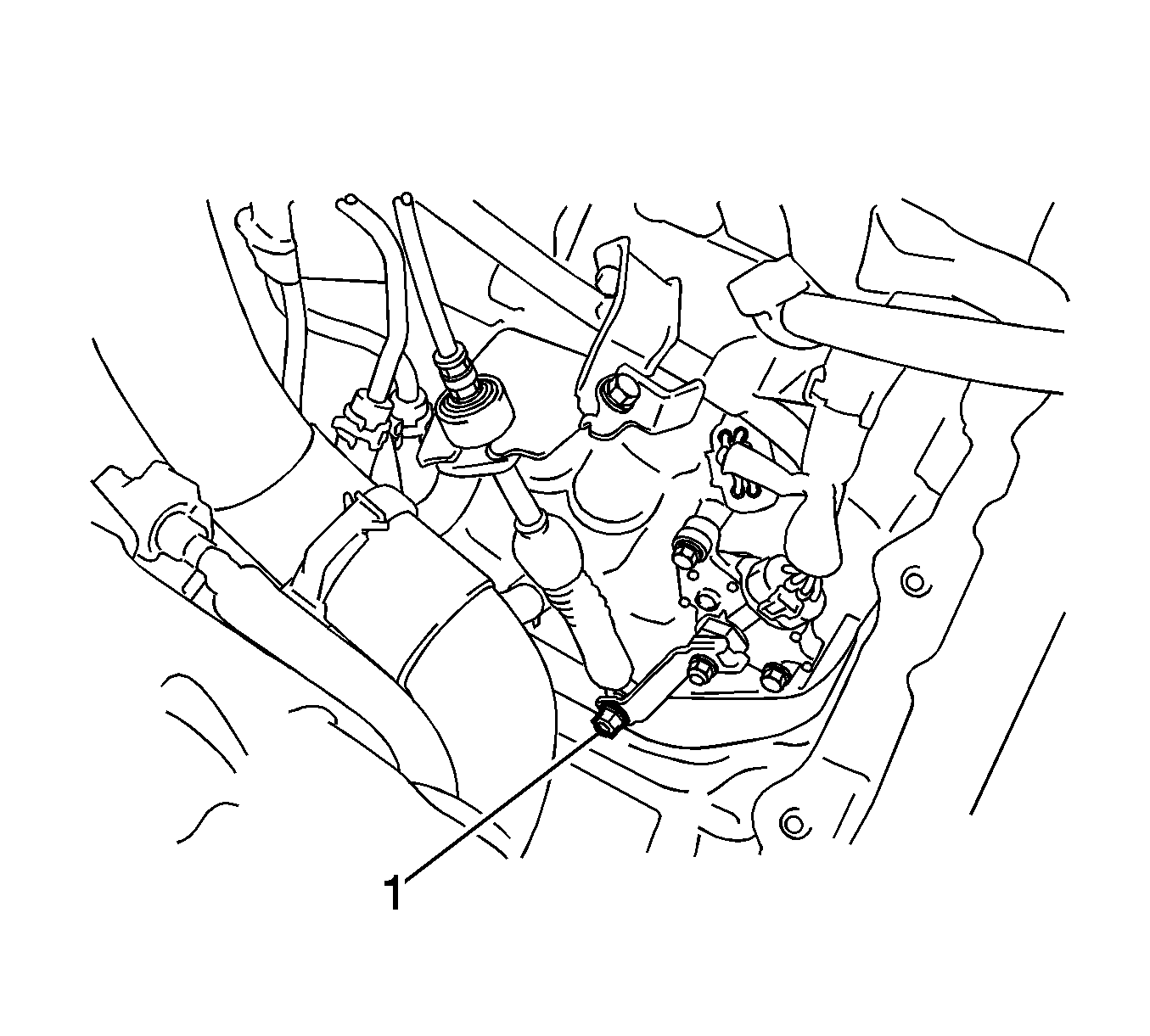
- Remove the nut (1) and disconnect the control cable assembly from the control shaft lever.
- Remove the clip and disconnect the transmission control cable assembly from the control cable bracket.
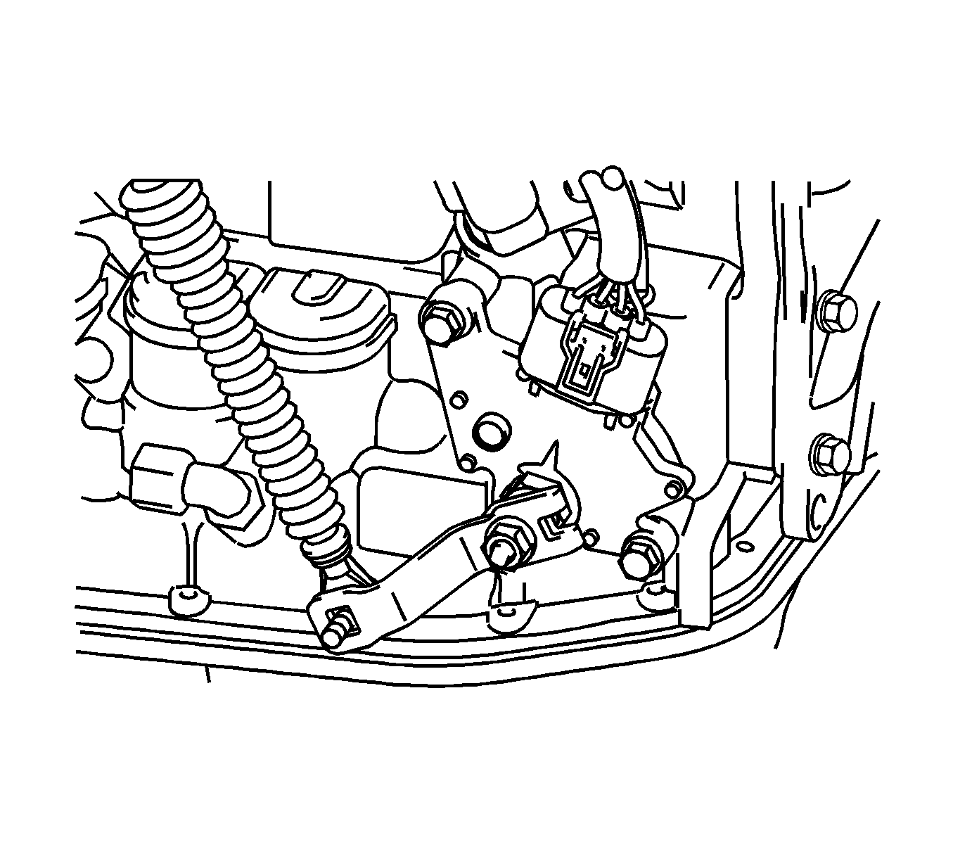
- Disconnect the park/neutral position switch connector.
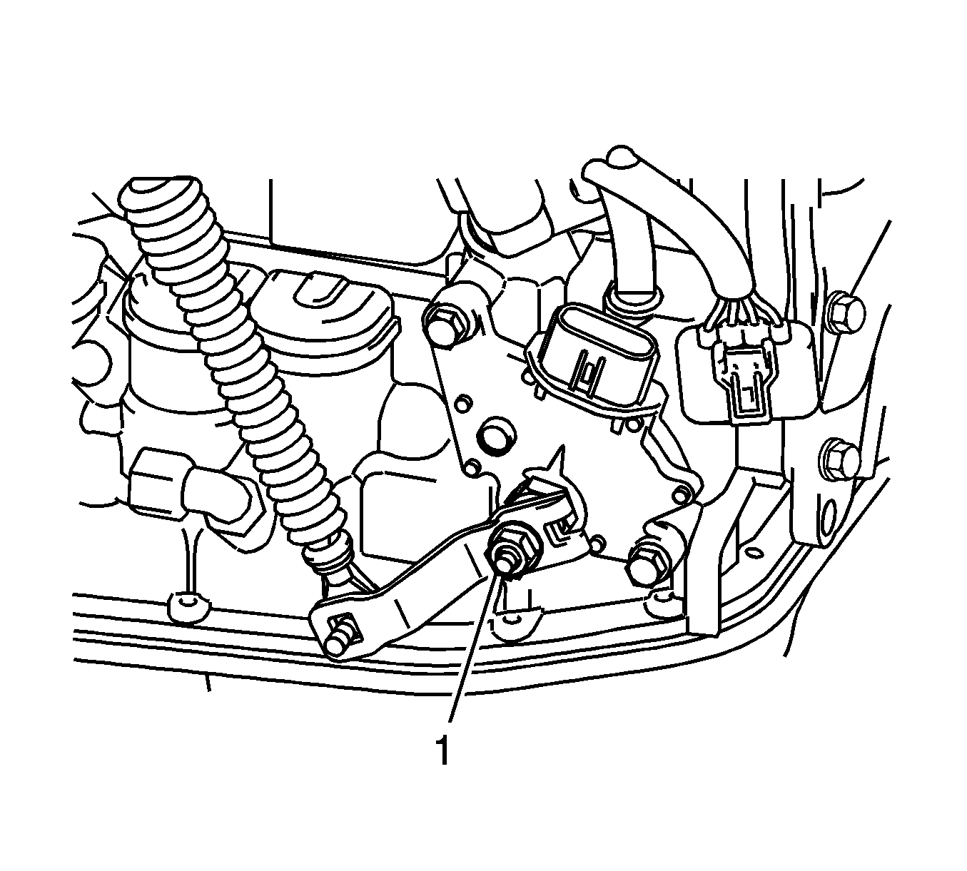
- Remove the nut (1), washer and control shaft lever.
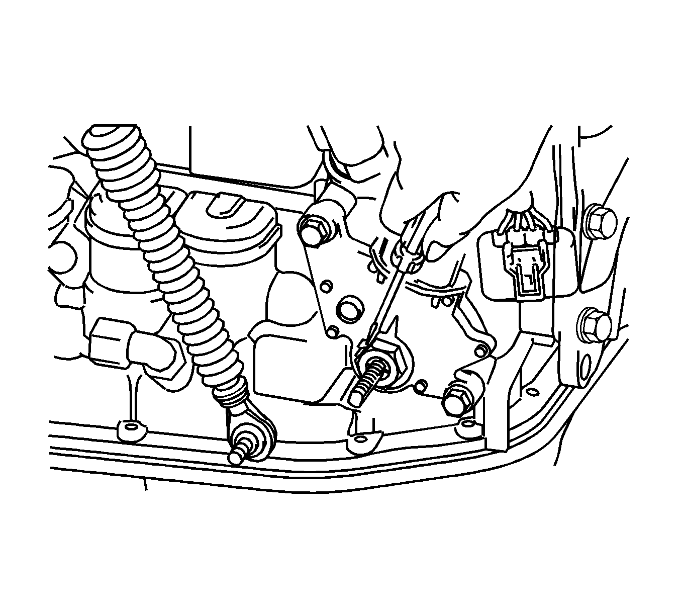
- Using a screwdriver, pry off the lock plate.
- Remove the nut and lock plate.
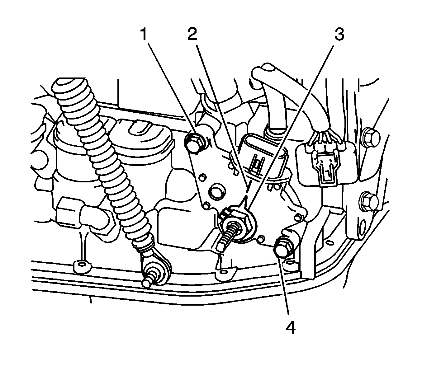
- Remove the bolts (1, 2) and pull out the switch.
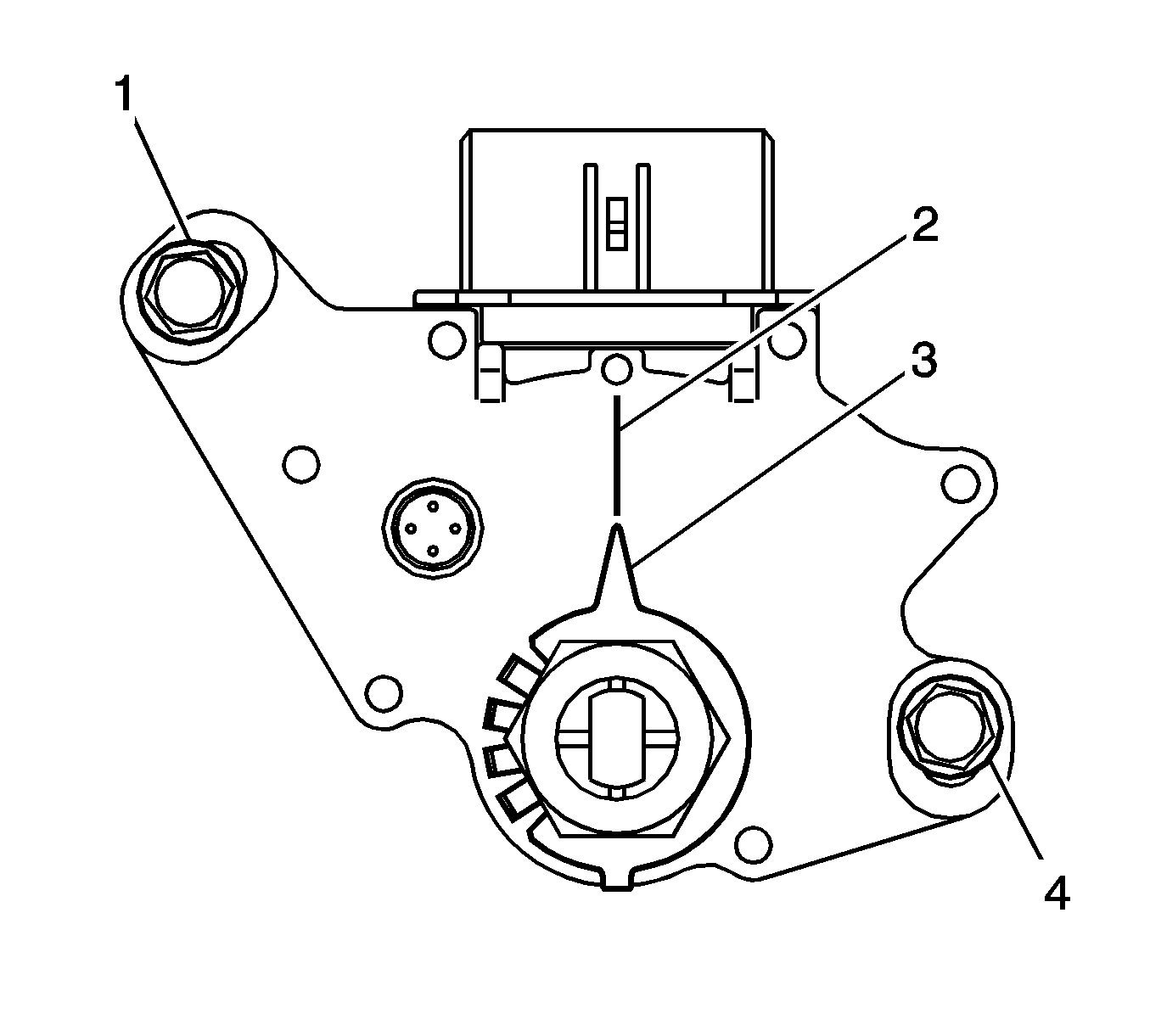
- Loosen the bolts (1, 4) of the switch and set the shift lever to the N position (2).
- Align the groove and neutral basic line (2).
- Hold the switch in this position and tighten the bolts (1, 4) to 5 N·m (448 lb in).
- After adjustment, perform the inspection.
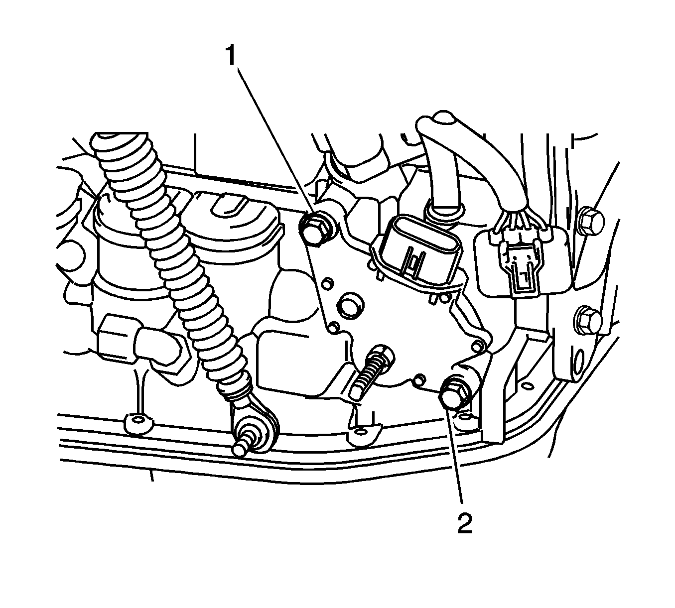
If operation cannot be done as specified, replace the park/neutral position switch.
Caution: Refer to Fastener Caution in the Preface section.
Installation Procedure
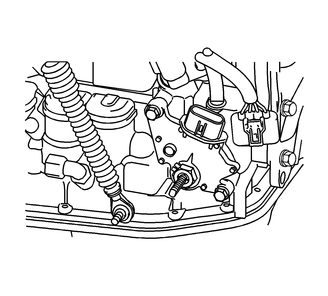
- Install the switch to the manual valve shaft.
- Hand tighten the bolts (1, 2).
- Install a new lock plate and tighten the manual valve shaft nut to 7 N·m (62 lb in).
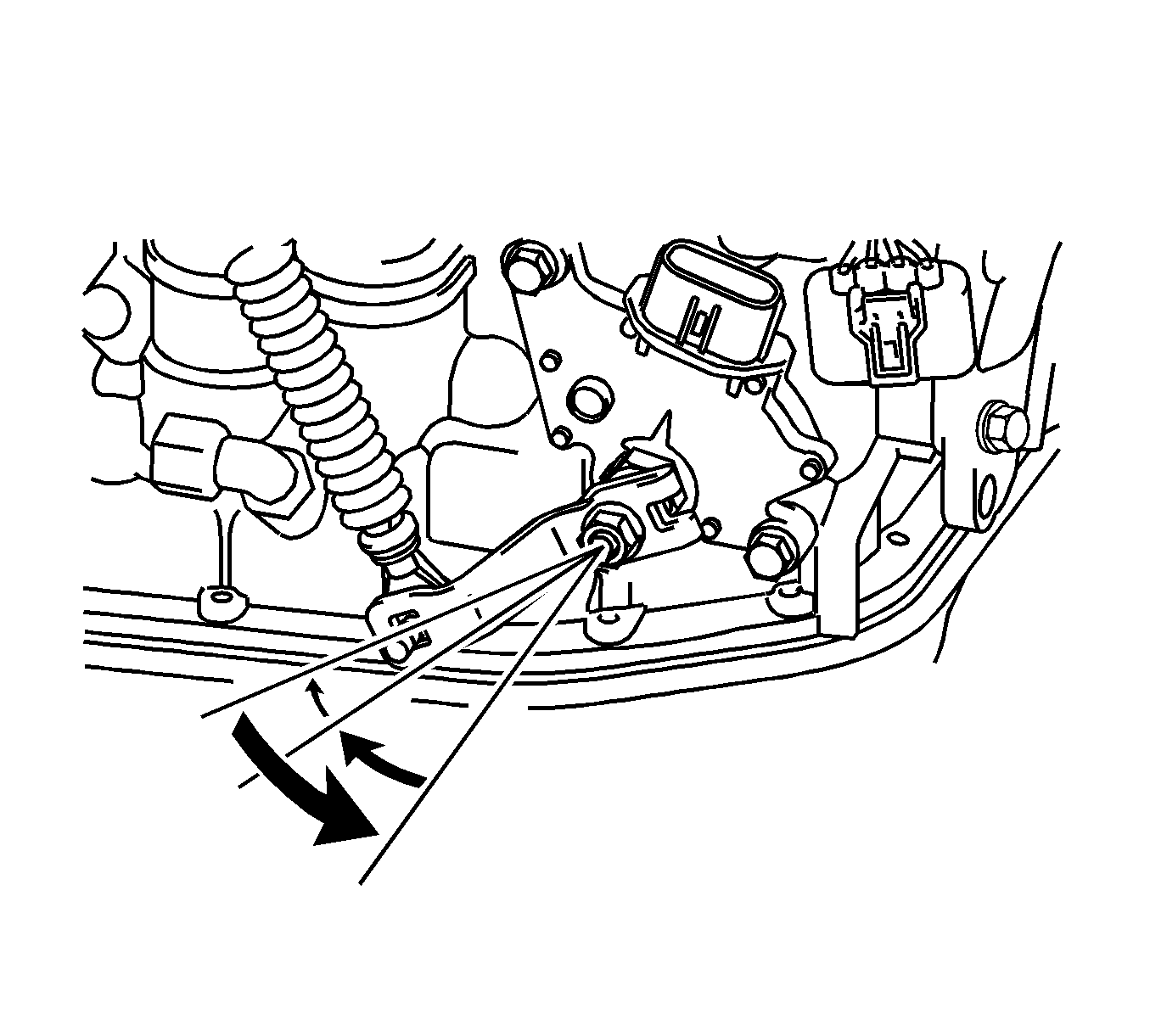
- Hand tighten the control shaft lever.
- Turn the lever counterclockwise until it stops, and then turn it clockwise two notches.
- Remove the control shaft lever.
- Align the groove with neutral base line (2).
- Hold the switch in this position and tighten the bolts (1, 4) to 5 N·m (44 lb in).
- Using a screwdriver, stake the nut with the lock plate.
- Install the control shaft lever with the washer and nut (1) and tighten to 13 N·m (115 lb in).
- Connect the switch connector.
- Connect the transmission control cable to the bracket with a new clip.
- Connect the transmission control cable assembly to the control shaft lever with the nut (1) and tighten to 15 N·m (11 lb ft).
- Install the battery tray. Refer to Battery Tray Replacement.
- Install the battery. Refer to Battery Replacement.
- Connect the negative battery cable to the battery. Refer to Battery Negative Cable Disconnection and Connection.
- Adjust the shift lever position.



Caution: Refer to Fastener Caution in the Preface section.
