For 1990-2009 cars only
Removal Procedure
- Disconnect the negative battery cable. Refer to Battery Negative Cable Disconnection and Connection.
- Remove the instrument cluster. Refer to Instrument Cluster Replacement.
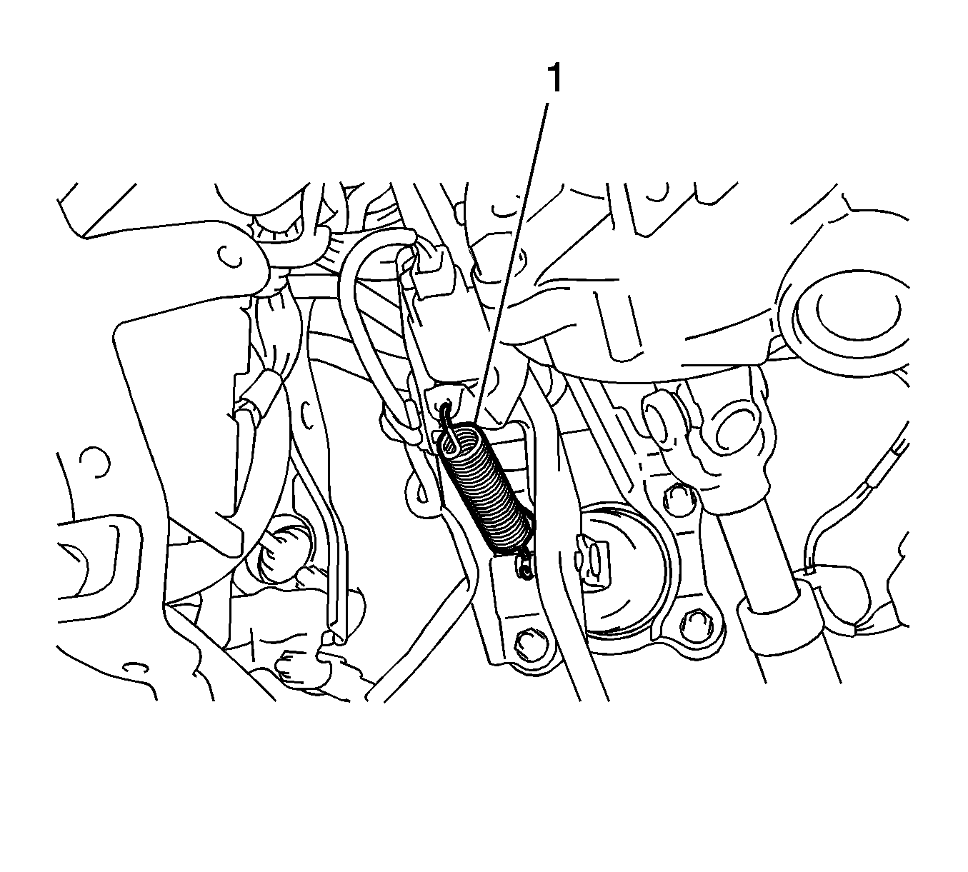
- Remove the brake pedal return spring (1) from the brake pedal support.
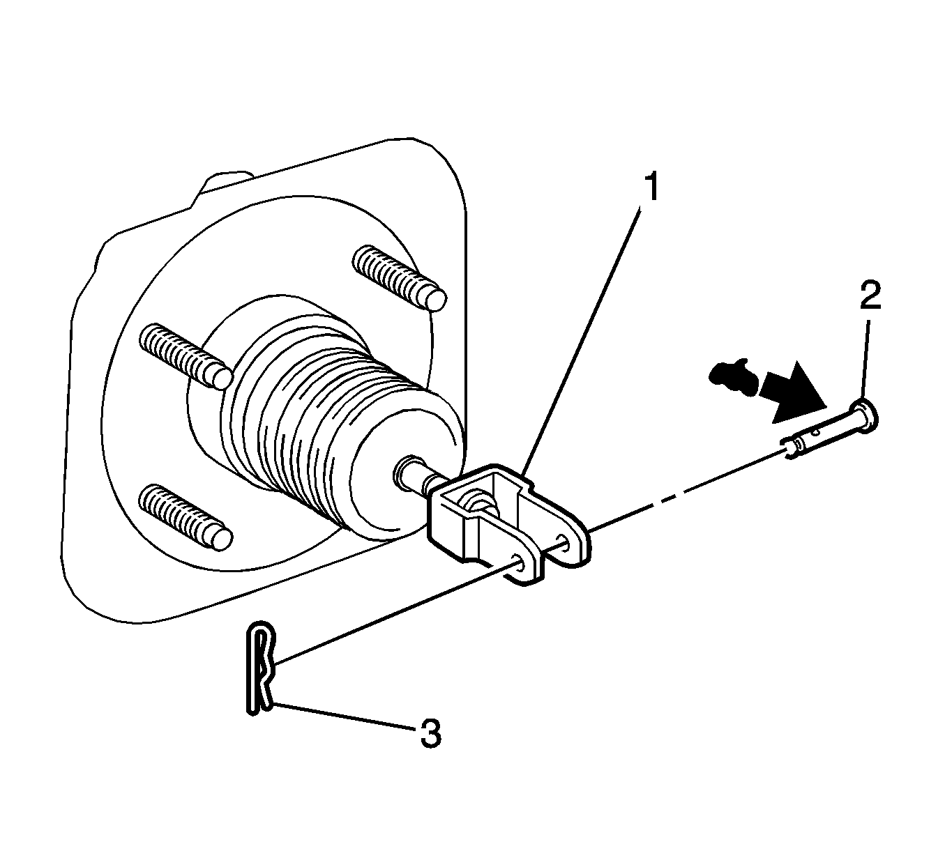
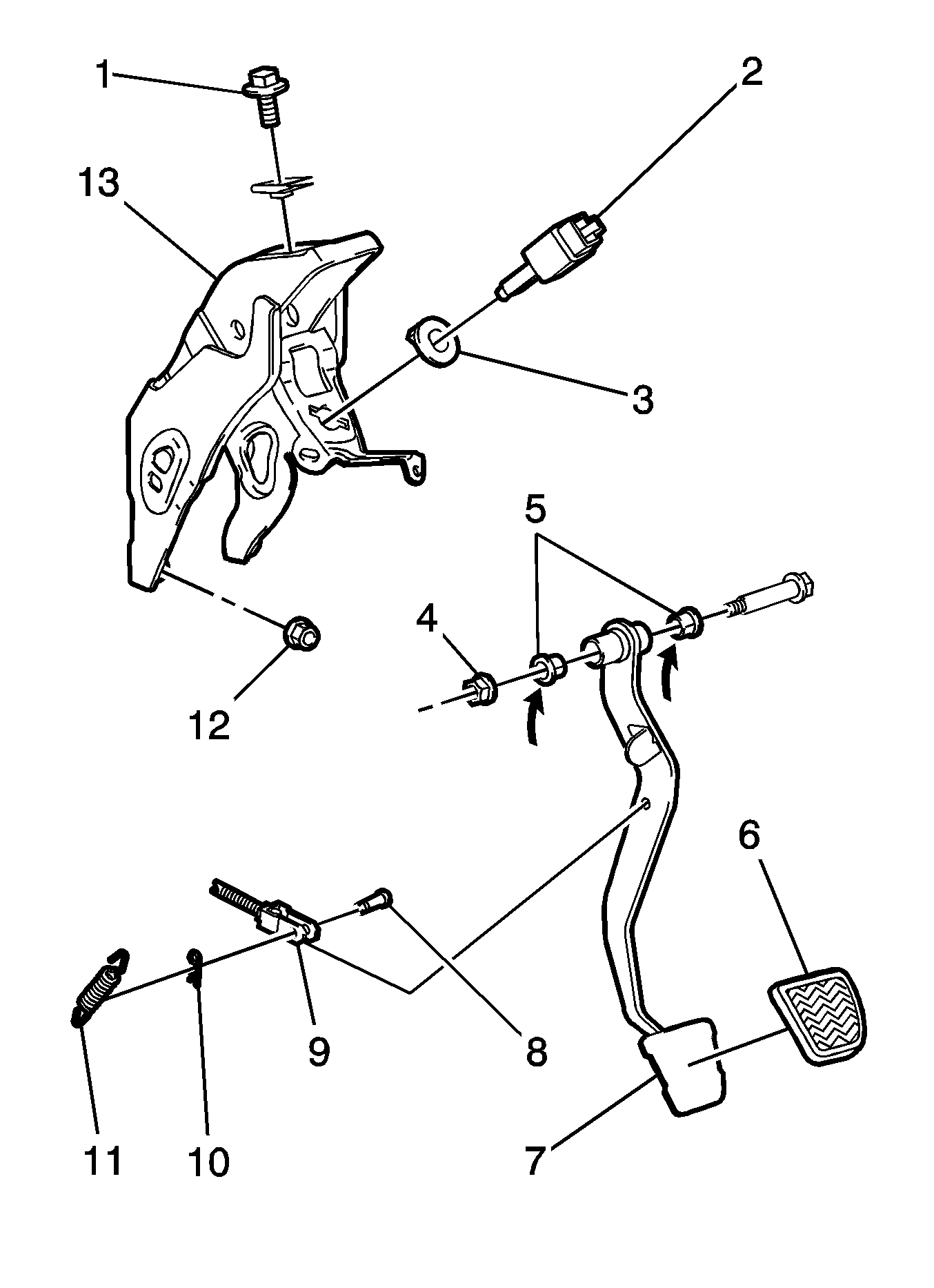
- Remove the clip (3) from the push rod clevis pin (2).
- Remove the push rod clevis pin from the push rod clevis (1).
- Separate the push rod clevis from the brake pedal.
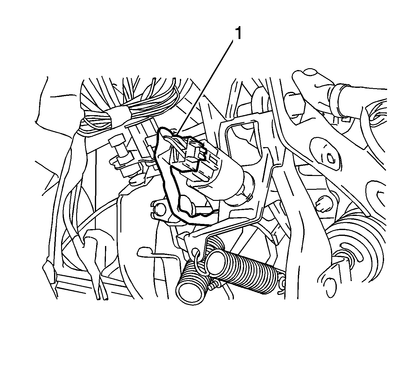
- Disconnect the stop lamp switch connector (1).
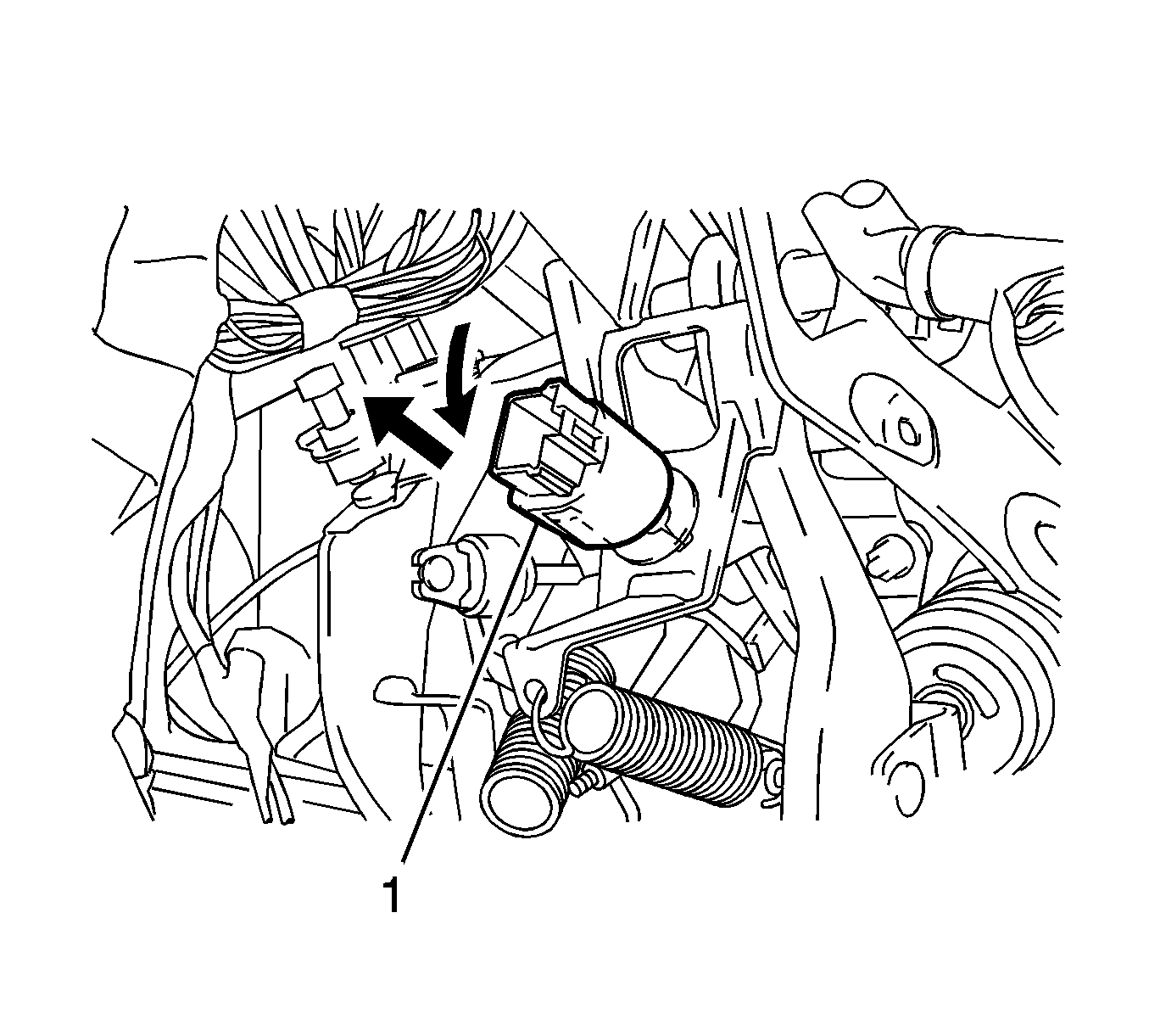
- Turn the stop lamp switch (1) counter clockwise and remove the stop lamp switch.
- Remove the stop lamp switch mounting adjuster from the brake pedal support.
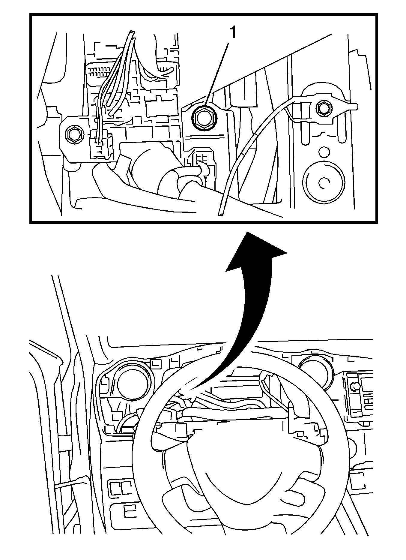
- Remove the bolt (1) and separate the brake pedal support from the instrument panel reinforcement.
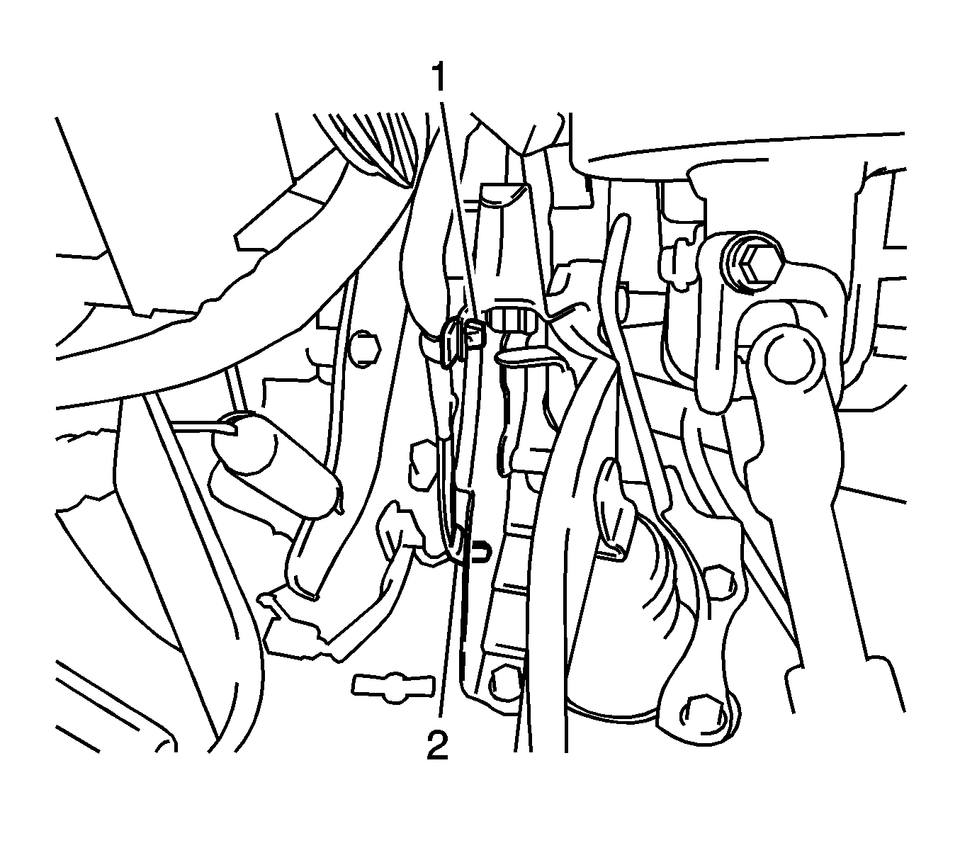
- Disengage the 2 clamps (1) from the brake pedal support.
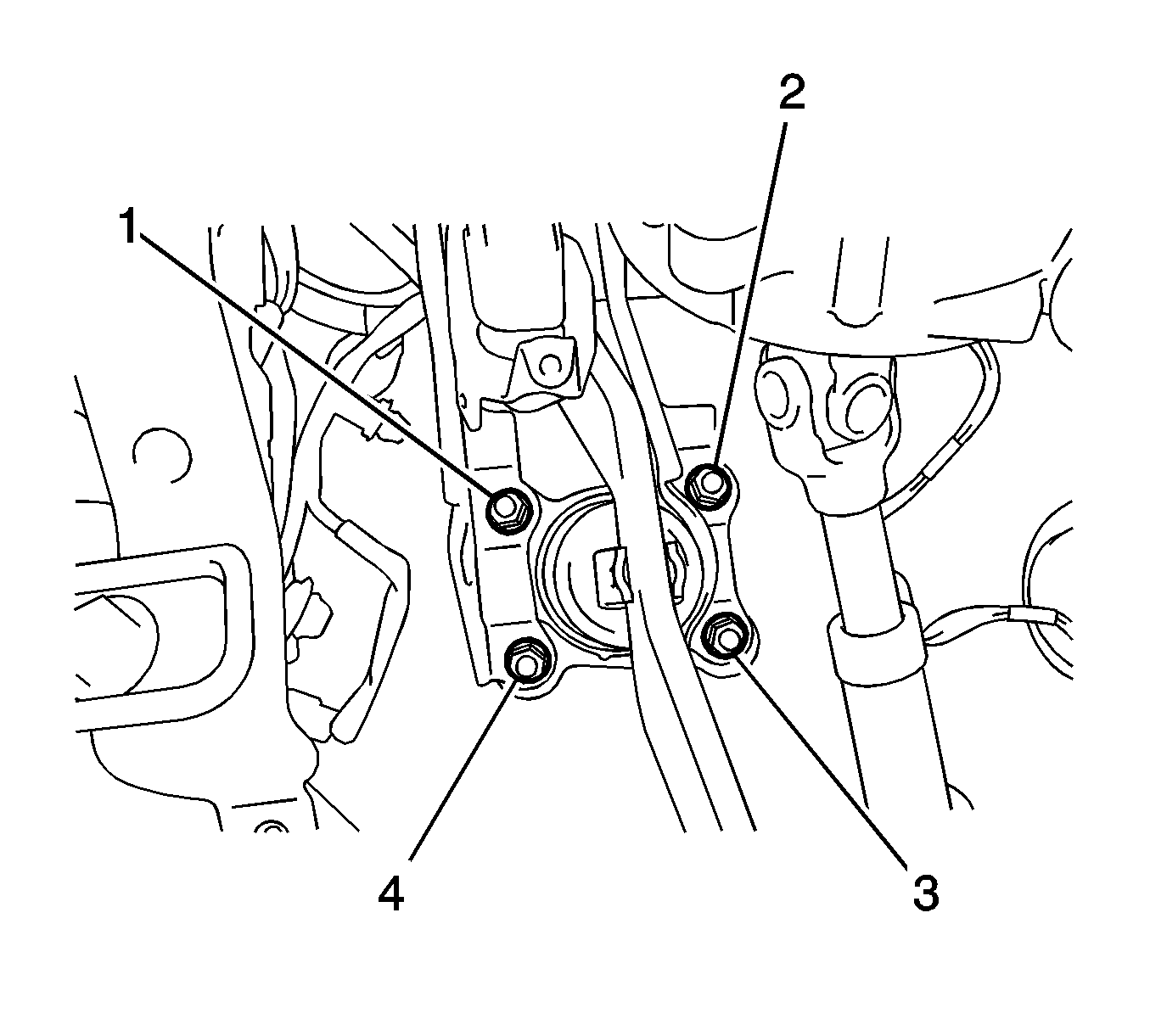
- Remove the 4 nuts (1, 2, 3, 4) and the brake pedal support from the vehicle.
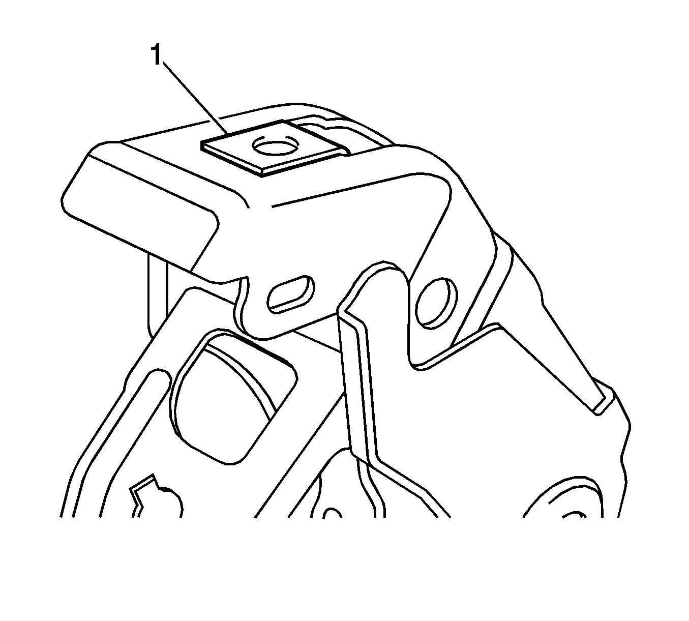
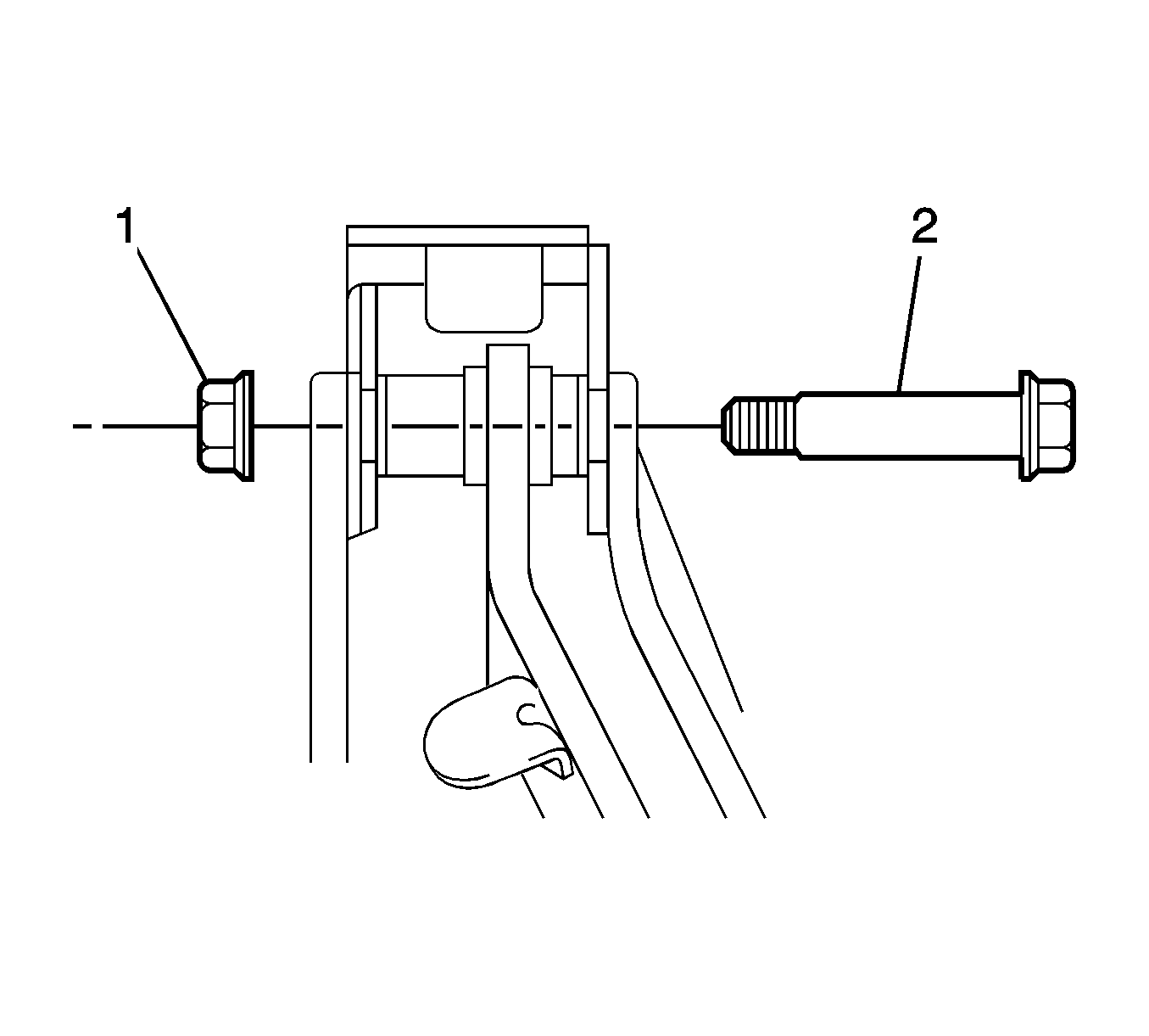
- Remove the nut (1) from the brake pedal support.
- Remove the shaft bolt (2) and the nut (1).
- Remove the pedal (7) from the support (13).
- Remove the 2 bushings (5) from the pedal.
- Remove the cover (6) from the pedal.
Discard the clip.
Discard the bushings.
Installation Procedure
- Install the cover (6) to the brake pedal (7).
- Apply lithium soap base glycol grease to 2 NEW bushings (5).
- Install the bushings to the pedal.
- Install the pedal to the support (13).
- Install the nut (1) to the shaft bolt and tighten to 37 N·m (27 lb ft).
- Install the nut (1) to the brake pedal support.
- Install the support to the vehicle with the 4 nuts (1, 2, 3, 4) and tighten to 13 N·m (115 lb in).
- Engage the 2 clamps (1) to the brake pedal support.
- Install the brake pedal support to the instrument panel reinforcement with the bolt (1) and tighten to 24 N·m (18 lb ft).
- Install the stop lamp switch mounting adjuster to the brake pedal support.
- Install the stop lamp switch (1) until the rod hits the cushion.
- Turn the stop lamp switch 90 degrees clockwise.
- Adjust the stop lamp clearance. Refer to Stop Lamp Switch Adjustment.
- Connect the stoplamp switch connector (1).
- Apply lithium soap base glycol grease to the push rod clevis pin (2) and to the clevis pin hole in the pedal.
- Install the push rod clevis pin in order to retain the push rod clevis (1) to the pedal.
- Install a NEW clip (3) in order to retain the clevis pin to the pedal.
- Install the brake pedal return spring (1) between the brake pedal support and the push rod clevis.
- Measure the brake pedal travel. Adjust if necessary. Refer to Brake Pedal Travel Measurement and Inspection.
- Install the instrument cluster. Refer to Instrument Cluster Replacement.
- Connect the negative battery cable. Refer to Battery Negative Cable Disconnection and Connection.

Caution: Refer to Fastener Caution in the Preface section.


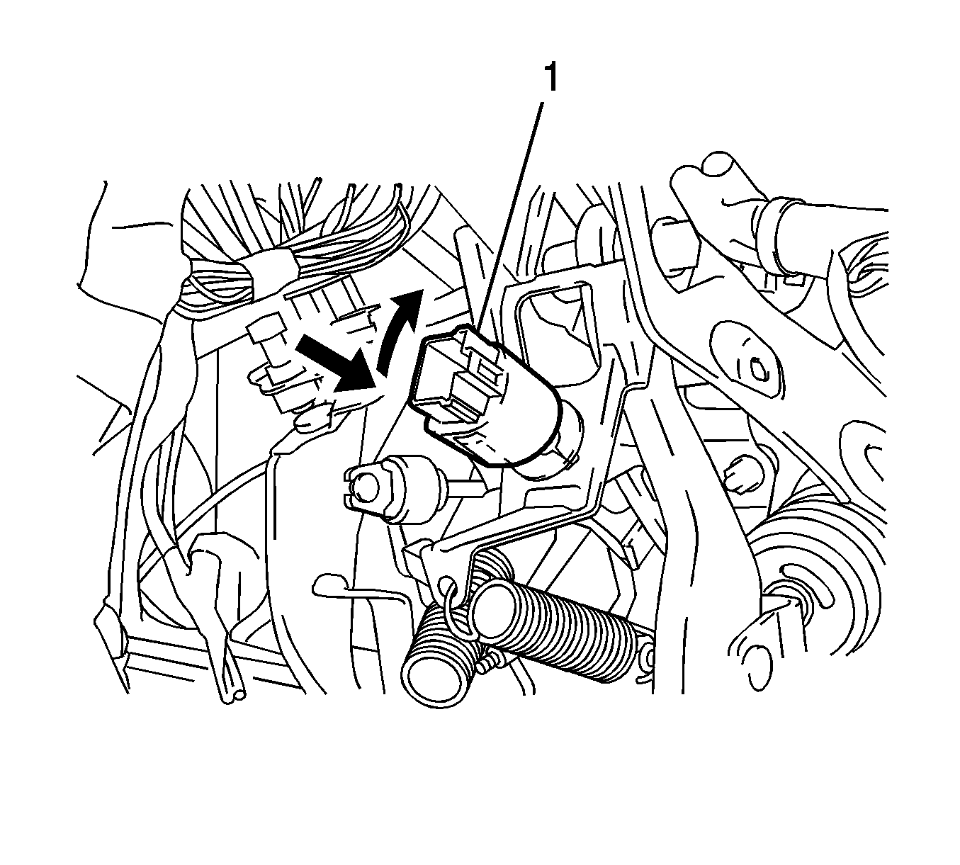
Note: While installing the stop lamp switch, support the pedal from behind in order to prevent pushing the pedal in.


